Modules
The settings are divided into different modules. Settings can be modified through both the UR Cap and through the QuickPick 303 web interface, via the respective Advanced tabs (Figures 1A and 1B).
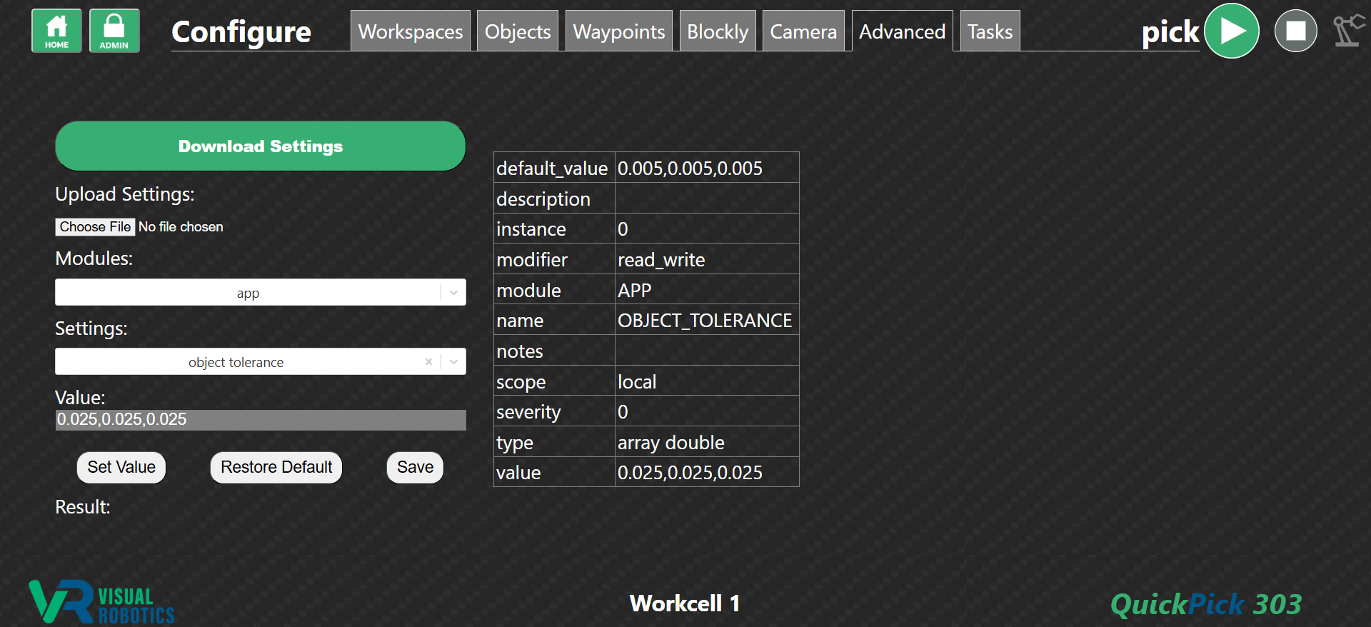
Figure 1A: Advanced Tab in the QuickPick 303 web interface
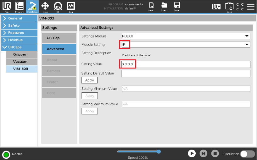
Figure 1B: Advanced Tab in the UR Cap
Select the desired module in the pulldown menu (Figure 2) then select the desired setting in the pulldown menu below that. The Advanced tab shows the current, default, and allowable values for each setting. Refer to the User Interface Manual for details on how to change settings.
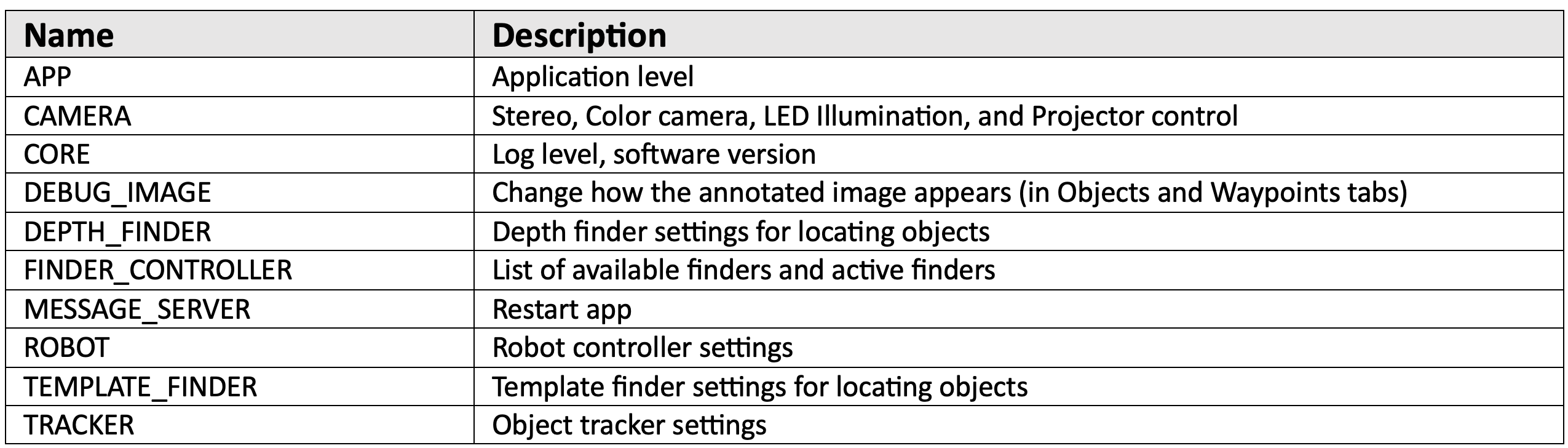
Figure 2: Settings Modules
Module Settings
The following sections tabulate the settings for each module.
APP
Application-level settings not otherwise categorized.

Figure 3: APP Module Settings
The APP module is typically modified by the QuickPick-303 software itself, not normally modified by the Programmer.
CAMERA
Stereo Camera, Inspection Camera, LEDs, and Stereo Projector settings.
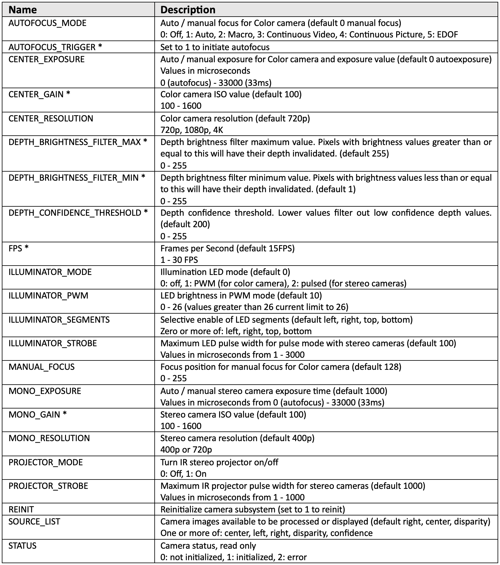
Figure 4: CAMERA Module Settings
*These parameters are unlikely to be changed from default.
Some setting changes to the CAMERA module require a camera REINIT: CENTER_RESOLUTION, MONO_RESOLUTION, SOURCE_LIST
CORE
Location of settings not otherwise assigned to other modules.
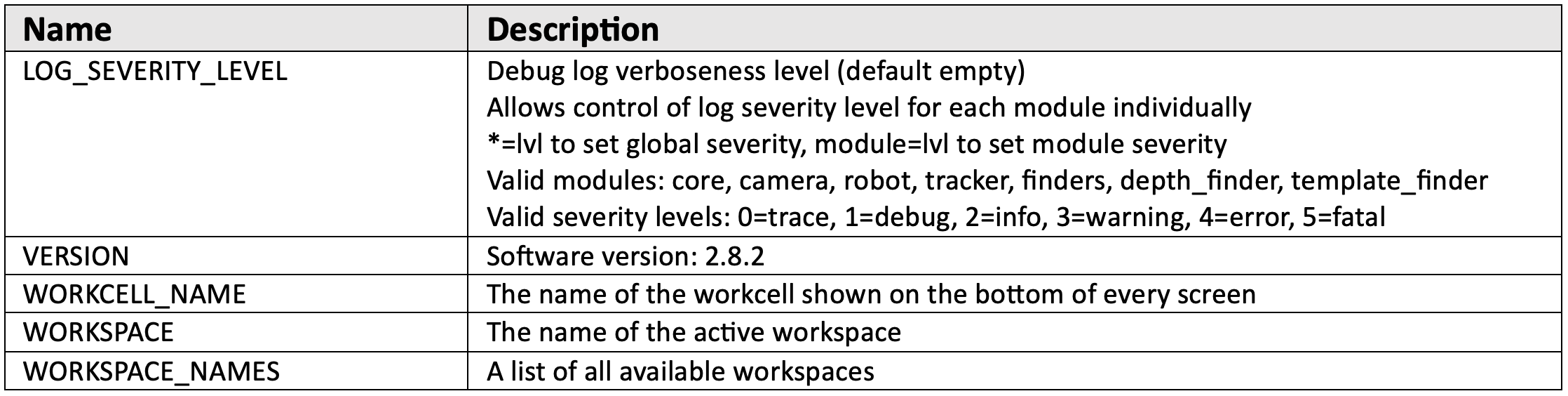
Figure 5: CORE Module Settings
DEBUG IMAGE
Configures the debug image that is displayed with “show objects”. The debug image can be very helpful for verifying the performance of the vision system. By default, objects that are identified or “found” are shown in color with a purple outline, while the rest of the image is grayscale and dimmed, to enhance the visibility of the identified objects. By default the name of the object (its classification) is shown. The programmer can enable other annotation features, such as showing the object dimensions or location, which may be helpful when developing programs. It takes time to create the annotated debug image, especially if there are a lot of objects in the field of view. Since VIM-303 is a real-time system, it may be important to limit the amount of time that the camera spends annotating the image. This is the purpose of the ANNOTATION_MODE and PERFORMANCE_TIMEOUT settings.
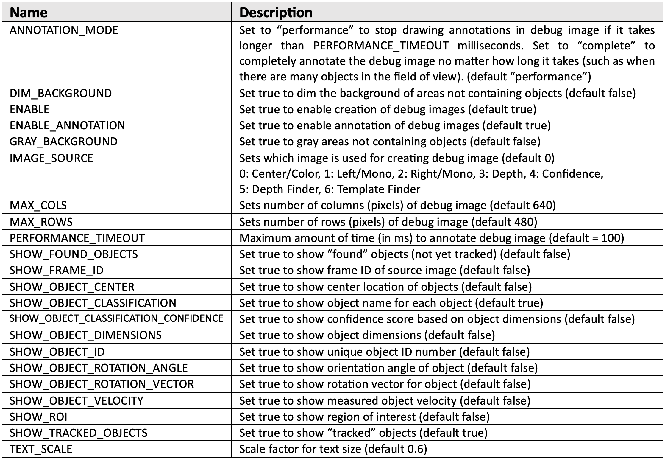
Figure 6: DEBUG IMAGE Module Settings
The default debug image is a 640x480 image from the Color camera with purple annotation around each tracked object with the object classification text indicated in yellow and the object shown in color.
DEPTH FINDER
The Depth Finder uses the 3D camera to detect objects in the field of view. The camera must be aimed straight down when using this finder. The finder can automatically detect a flat surface (known as the Table, whether or not it is an actual table) by detecting a surface that is a uniform distance from the camera and takes up a majority of the field of view. It can automatically detect objects that are on top of this surface. In some cases, the surface that objects are sitting on is relatively narrow. In that case AUTO_TABLE_HEIGHT can be set to false and the surface Z coordinate can be entered in the TRACKER module with the setting WORK_SURFACE_HEIGHT.
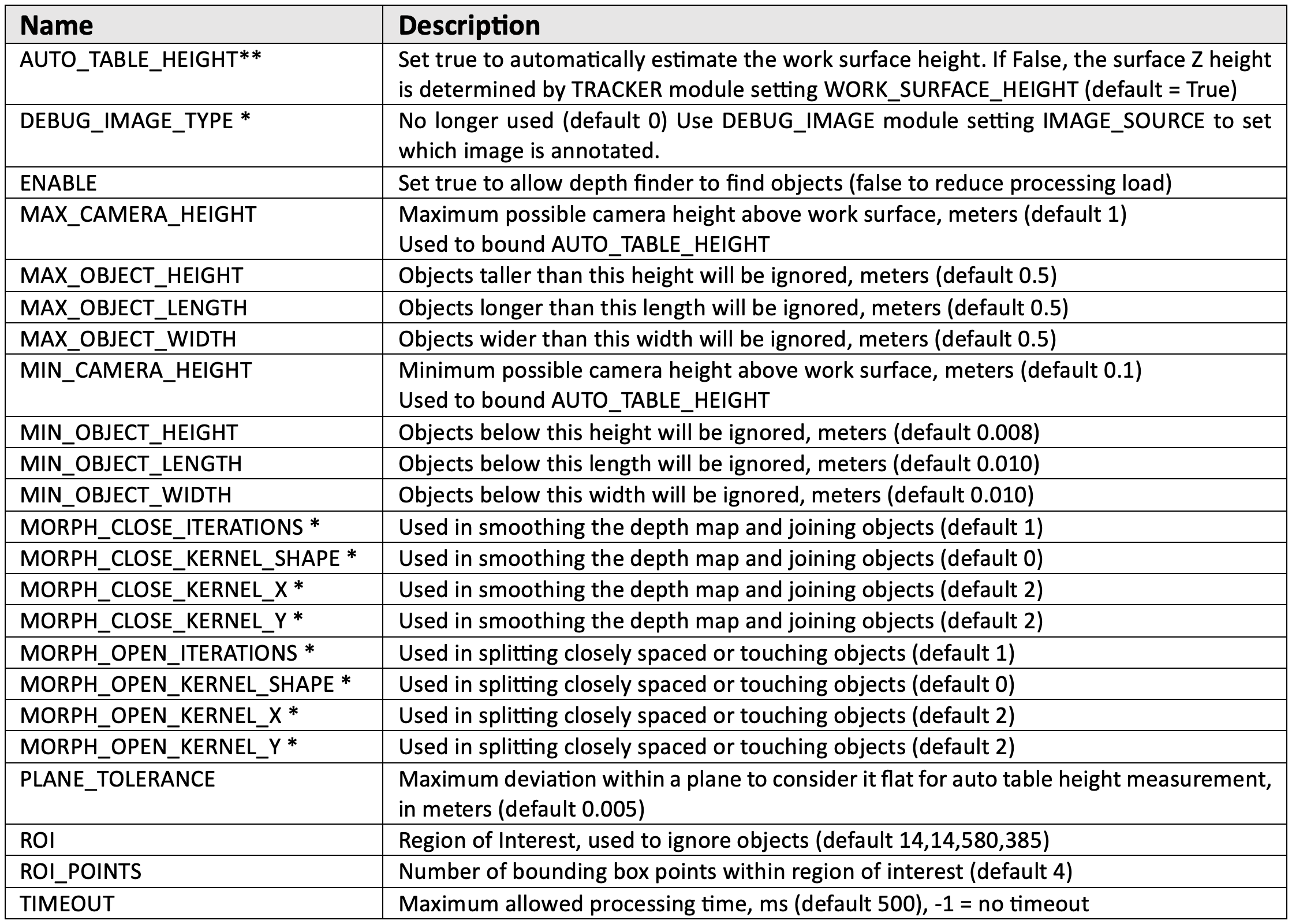
Figure 7: DEPTH FINDER Module Settings
*These parameters are unlikely to be changed from default.
**The Depth Finder can automatically detect the surface height (also known as Table Height) by seeing a majority of the stereo field of view being measured at substantially the same Z distance. For more complicated scenes, the AUTO_TABLE_HEIGHT should be set to false and the WORK_SURFACE_HEIGHT (really work surface depth, in TRACKER module) should be set to the Z distance (in m) from the front of the camera to the work surface.
FINDER CONTROLLER
The Finder Controller contains a list of all the available finders and the ones that are actively looking for objects. The more finders that are enabled, the slower the frame rate will be, as the processor sequentially processes the incoming images with each finder.

Figure 8: FINDER CONTROLLER Module Settings
*The FINDER_CONTROLLER should not have its values changed from default
MESSAGE SERVER
The Message Server module is used for internal inter-process communication. It has only one setting that a Programmer should ever modify. Setting RESTART_APP to 1 will restart the QuickPick application and underlying processes. This may be required to resolve unexpected camera behavior.

Figure 9: MESSAGE SERVER Module Settings
*These settings should not be changed from default.
ROBOT
The Robot module contains settings that affect the robot performance. It also specifies the host IP address of both the camera (HOST_IP) and the robot (IP).
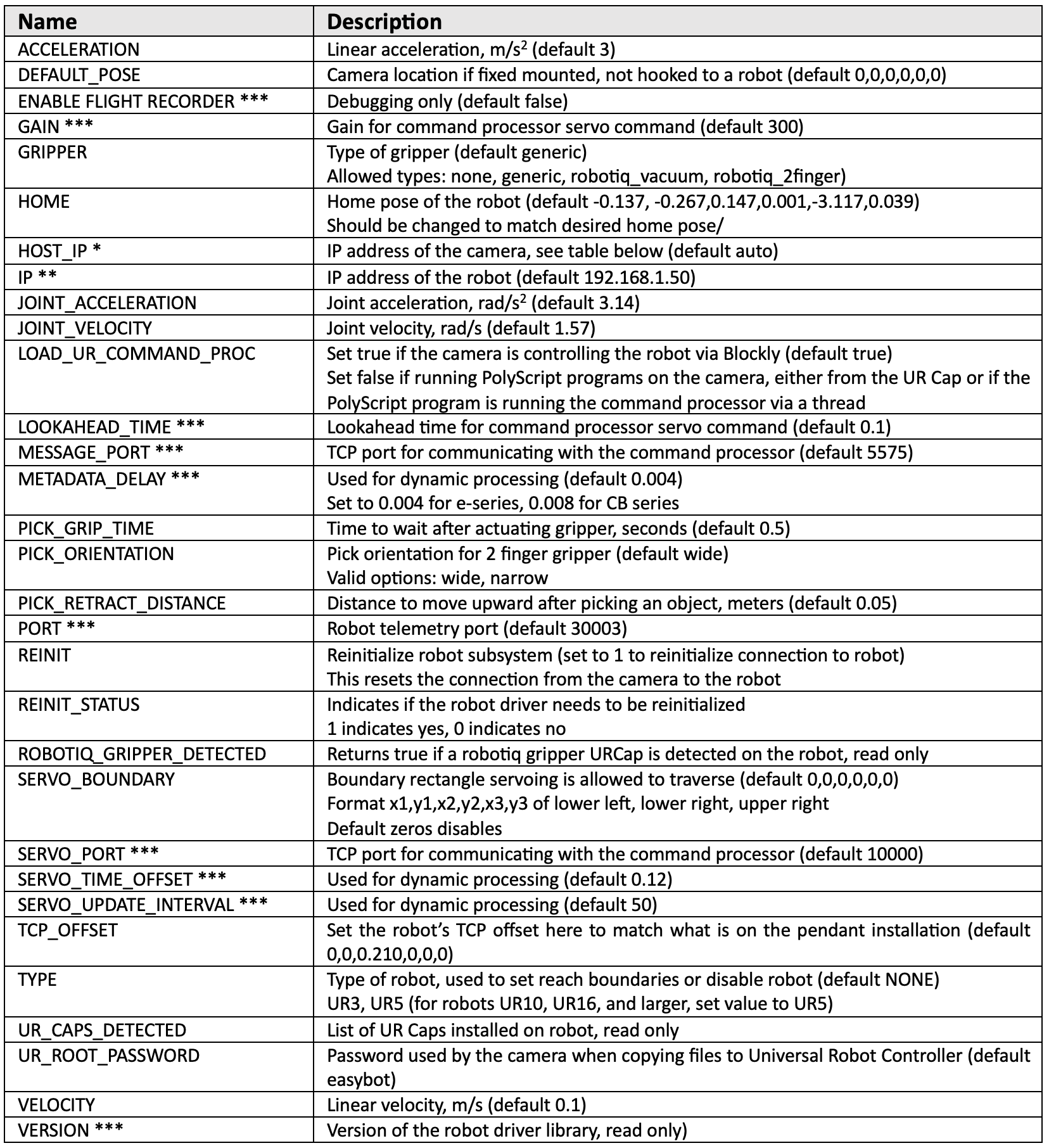
Figure 10: ROBOT Module Settings
*The HOST_IP table (Figure 11) shows the IP address of the camera based on the setting of HOST_IP and whether there is a DHCP server on the network. The camera HOST_IP defaults to auto which will get a DHCP address from a server or will set the camera’s address statically to 192.168.1.47 if there is no DHCP server.
**The robot’s IP address is set with the IP setting and must be reachable (on the same subnet) as the camera. The robot must be set to a static IP address.
***Do not change from default values.
The robot is controlled via a “command processor” PolyScript program that runs on the Universal Robot. This is typically initiated from the VIM-303 camera. If the programmer is using the UR Cap, the command processor is loaded by the UR Cap and LOAD_UR_COMMAND_PROC should be set to false. If a programmer is running their own PolyScope program on the robot’s pendant without using the UR Cap, the command processor program must be run as a thread in that program and the LOAD_UR_COMMAND_PROC setting should be set to False.

Figure 11: HOST_IP Table
TEMPLATE FINDER
The Template Finder locates objects in the 2D image that match a template. Templates are patterns of edges (a line drawing) of an object to be detected. Templates are defined by a captured template image that encompasses the object, and a set of parameters. Edges in the template image are calculated, and a determined number of these edges are used to create the template. Multiple templates are created at the specified scales and rotations. This set of templates is matched to the edges in a live image, and the best match is chosen if it exceeds the confidence level.
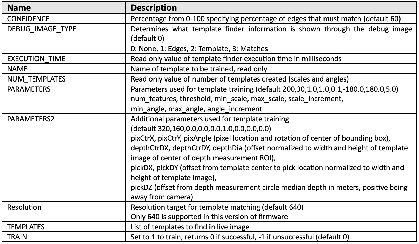
Figure 12: TEMPLATE_FINDER Module Settings
TRACKER
The Tracker creates a model of the location and motion of all objects that are currently or have recently been seen. Various settings set the behavior of the model. Of particular interest to the programmer are the settings BELT_VELOCITY, MAX_BELT_SPEED, STACKED_OBJECTS, TCP_CAMERA_OFFSET, VELOCITY_MODE, and WORK_SURFACE_HEIGHT. The behavior of the Tracker based on VELOCITY_MODE is shown in Figure 14. By default, the Depth Finder identifies objects by matching all of their dimensions (length, width, height) to the list of object templates. If STACKED_OBJECTS is set to True, then the height of the object will be ignored, allowing the Depth Finder to match a stack of objects.
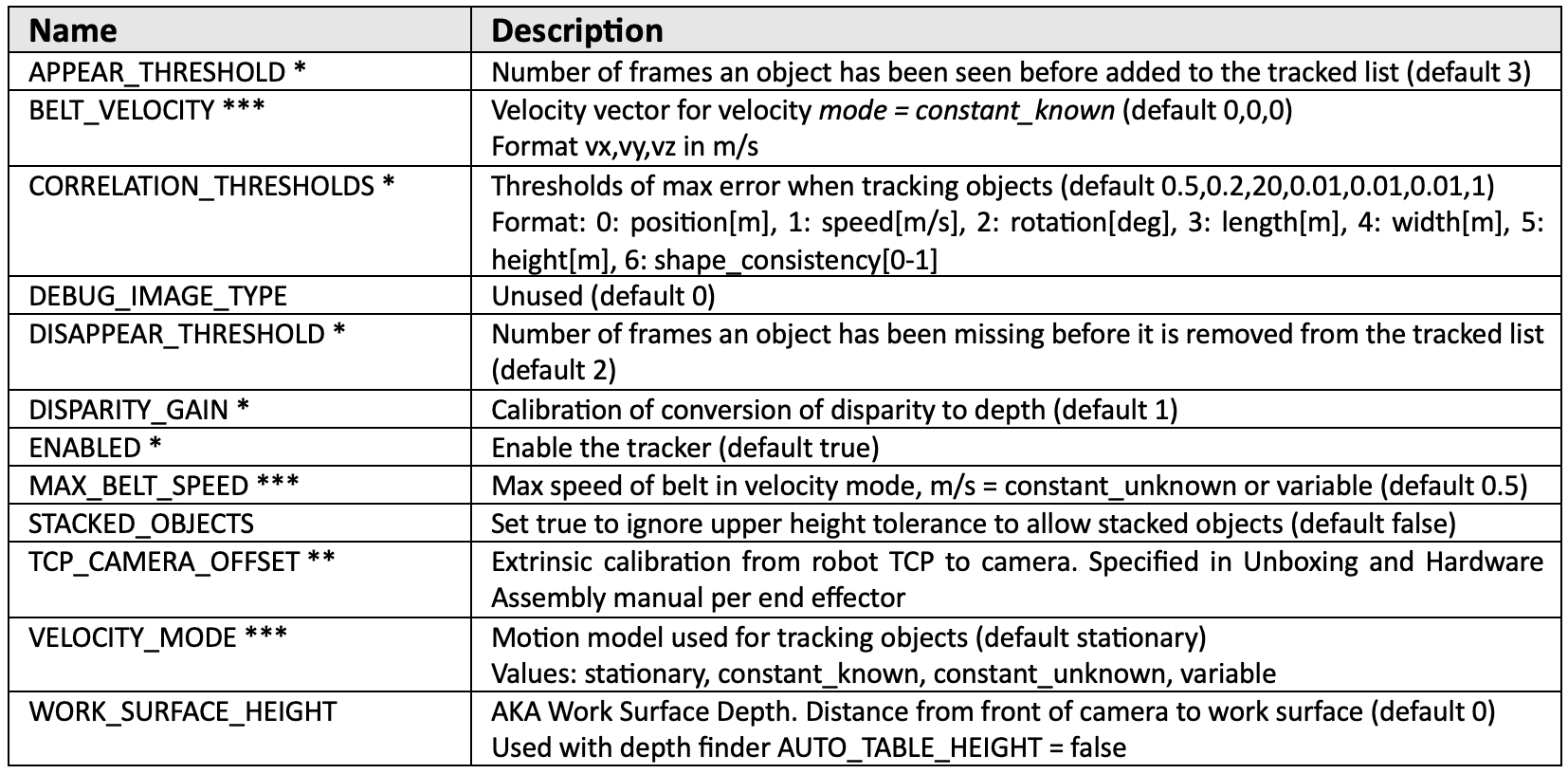
Figure 13: TRACKER Module Settings
*These settings should not be changed from default without careful consideration.
**This value depends on the camera mount and end effector. See the Unboxing and Hardware Assembly manual for values.
***The VIM-303 tracks objects optically by observing their motion from frame to frame and by knowing the location of the camera when the picture was taken using the patented Vision-In-Motion technology. The Tracker module uses the assumption from the VELOCITY_MODE setting to parameterize its motion model, described in Figure 14.
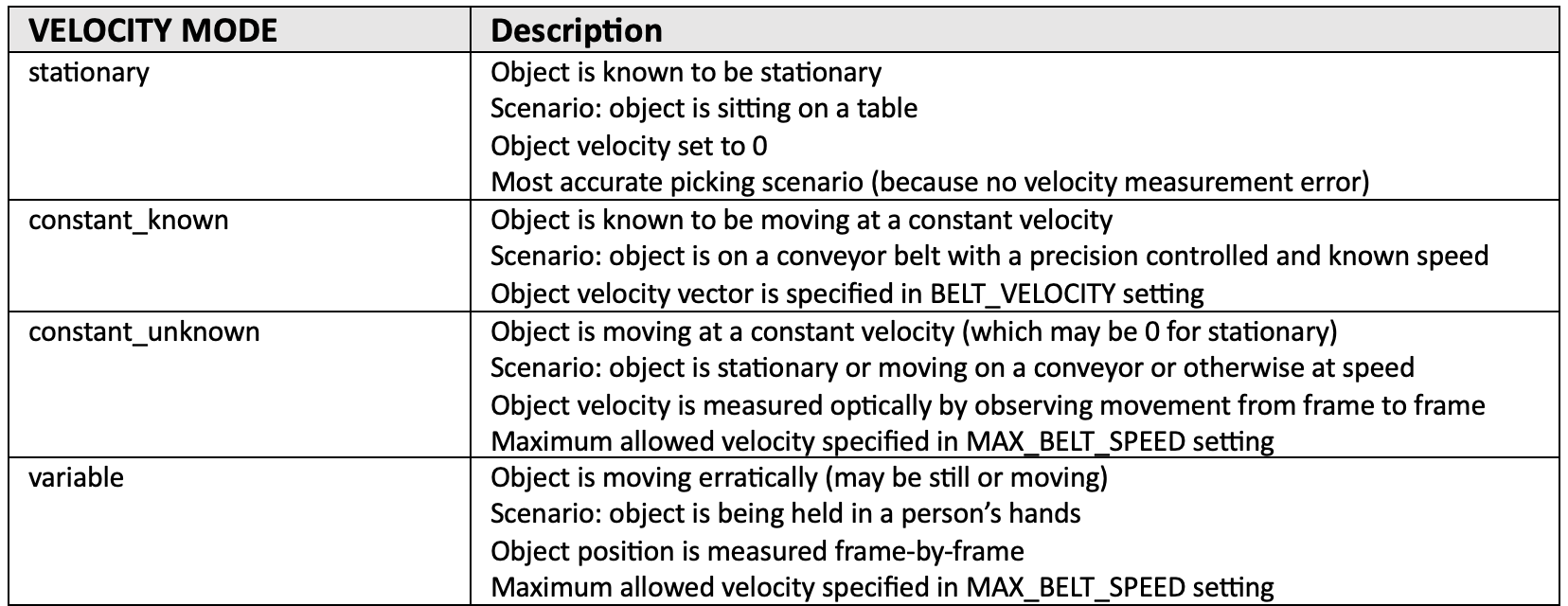
Figure 14: VELOCITY_MODE Settings