Template Object Configuration
The Template Finder detects objects based on their match to a template image.
Make sure you’ve created a new object as described above. Once you see the Object Editor dialog you’ll be given the choice of a finder for your object. Choose the Template tab and click Select Template Finder to begin the configuration and training process (Figure 36).
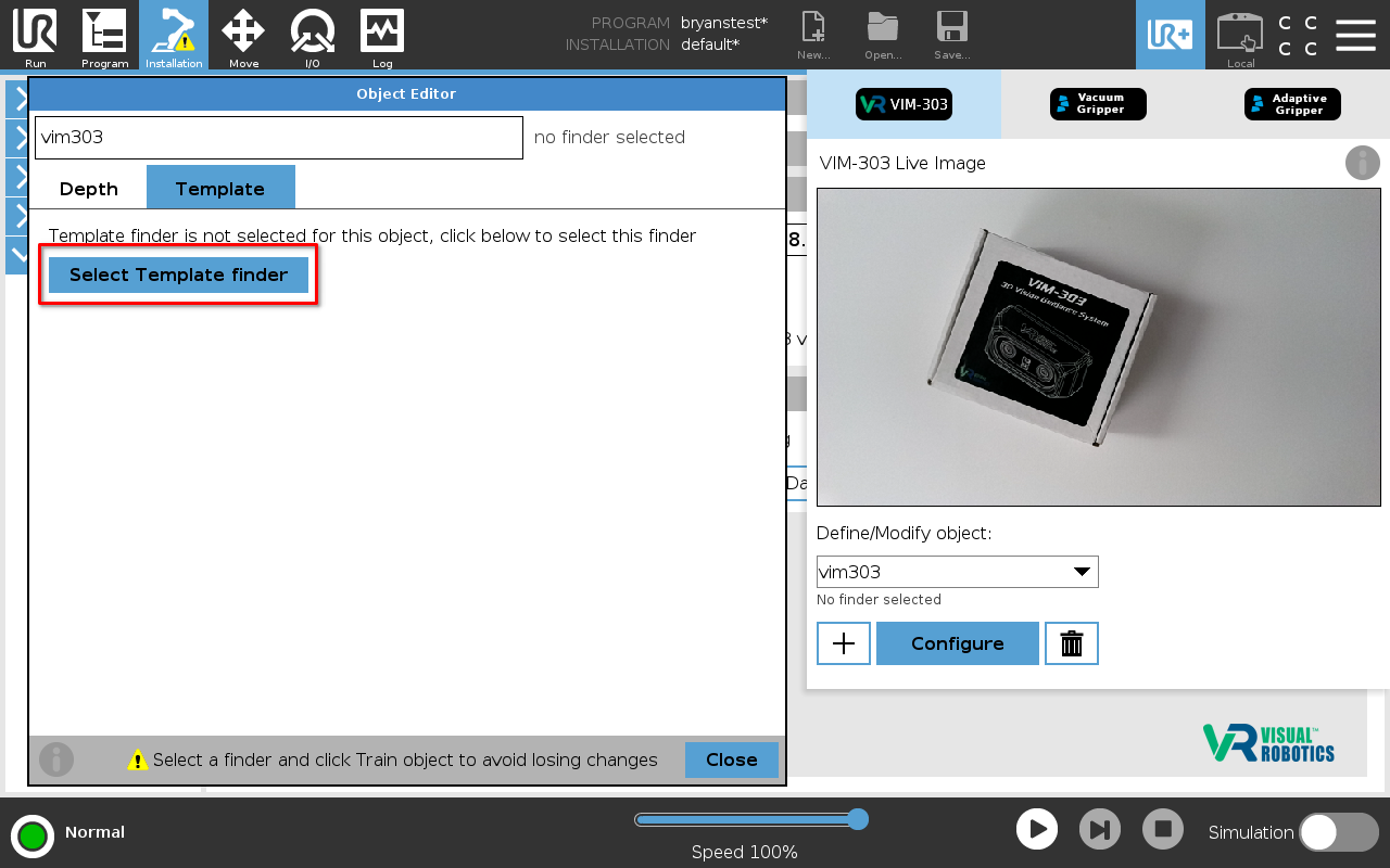
Figure 36: Select Template Finder
Defining the Template
Figure 37 shows the Object Editor template configuration page. The first step is to create a template image. Click Create Template to open the Template Maker dialog (Figure 38). Placing the object on a uniform background may be useful in order to train only edges corresponding to the object instead of the background.
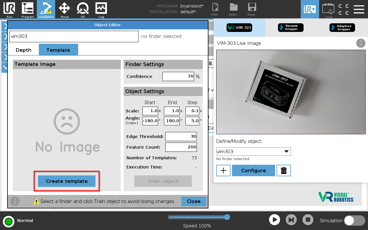
Figure 37: Template Object Editor
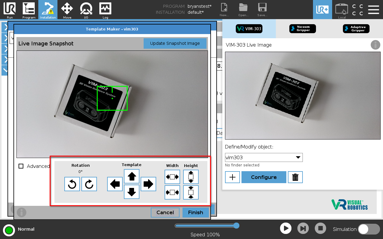
Figure 38: Template Maker
The green rectangle defines the ROI (region of interest) location, size, and orientation that defines the template image. The short green line (on the upper side of the green rectangle) specifies the orientation of the template. The camera will direct the robot to rotate the end effector until the camera sees the object oriented squarely with the template in this orientation.
Use the arrow buttons to move the ROI center point (shown as a green dot) left/right/up/down or touch the screen to select a spot to move to. Use the rotation arrow buttons to rotate the ROI around the center point. Use the arrow buttons on the right side to adjust the width and height.
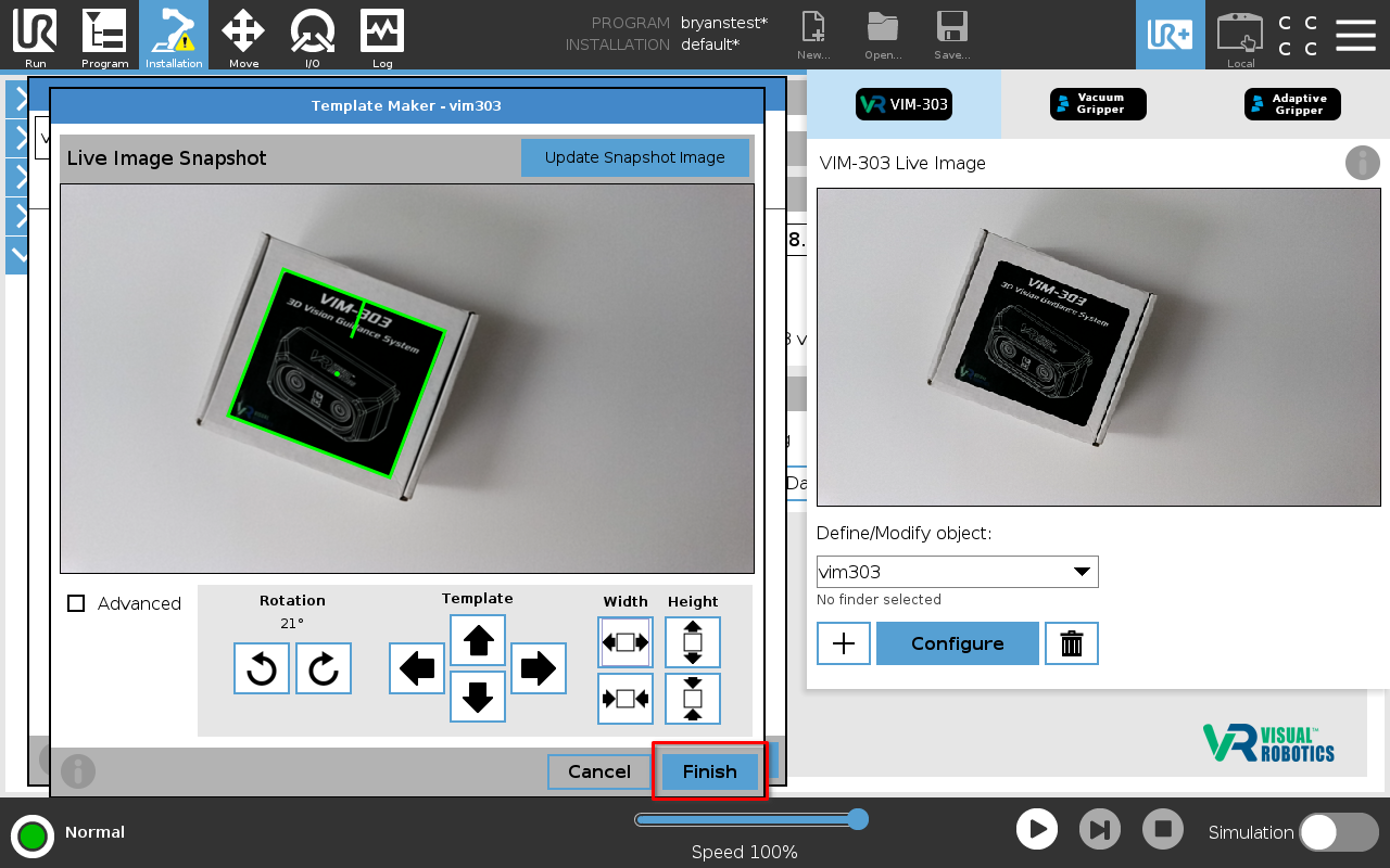
Figure 39: Template Maker with ROI set
Press Finish when the green ROI box is aligned properly with the object (Figure 39), resulting in the template image (Figure 40). When picking, the robot will move so that the end effector will be at the center of the object with the orientation matching this template from the camera’s perspective.
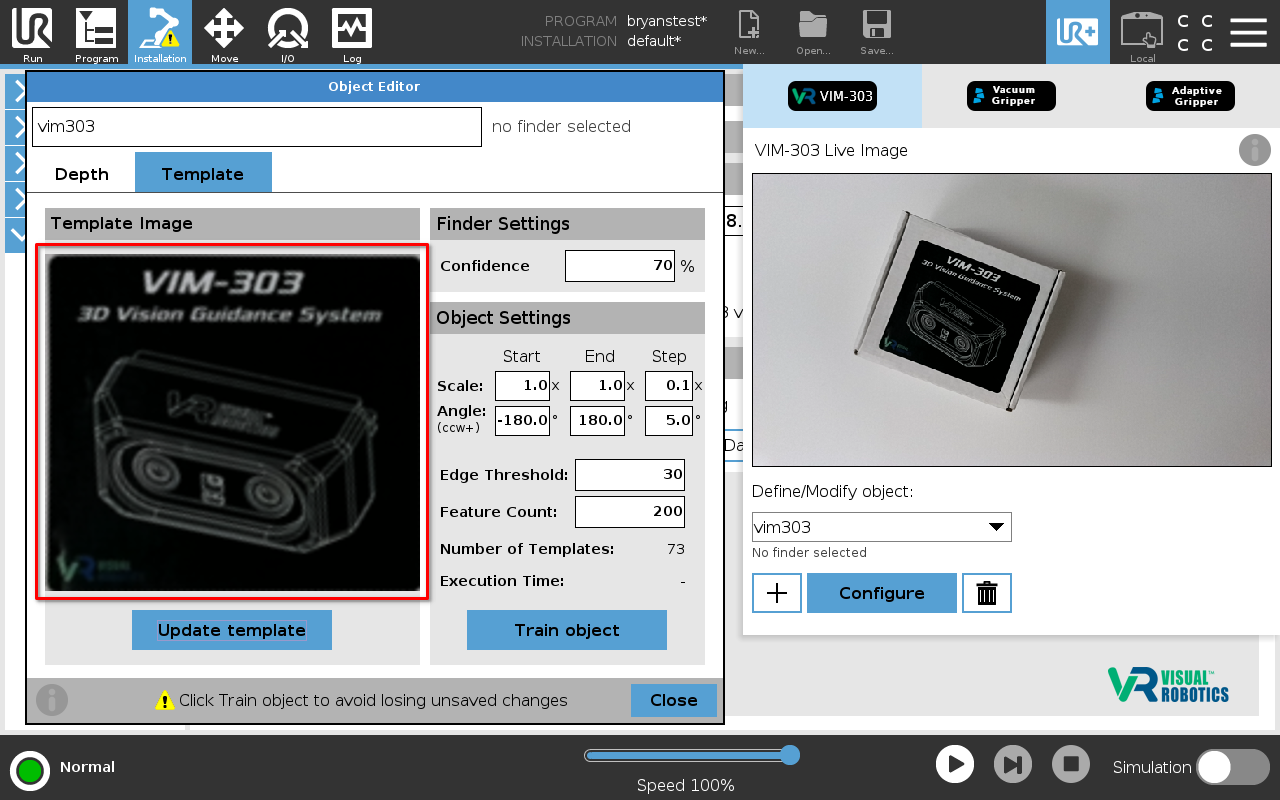
Figure 40: Template Object Editor
Advanced Template Settings
It is possible to set several additional parameters for how the camera interfaces with a template object. These settings become available when the Advanced checkbox is pressed in the Template Maker, as shown in Figure 41. Enabling this option brings up a different set of controls and adds a blue crosshair and a red circle (Figure 42).
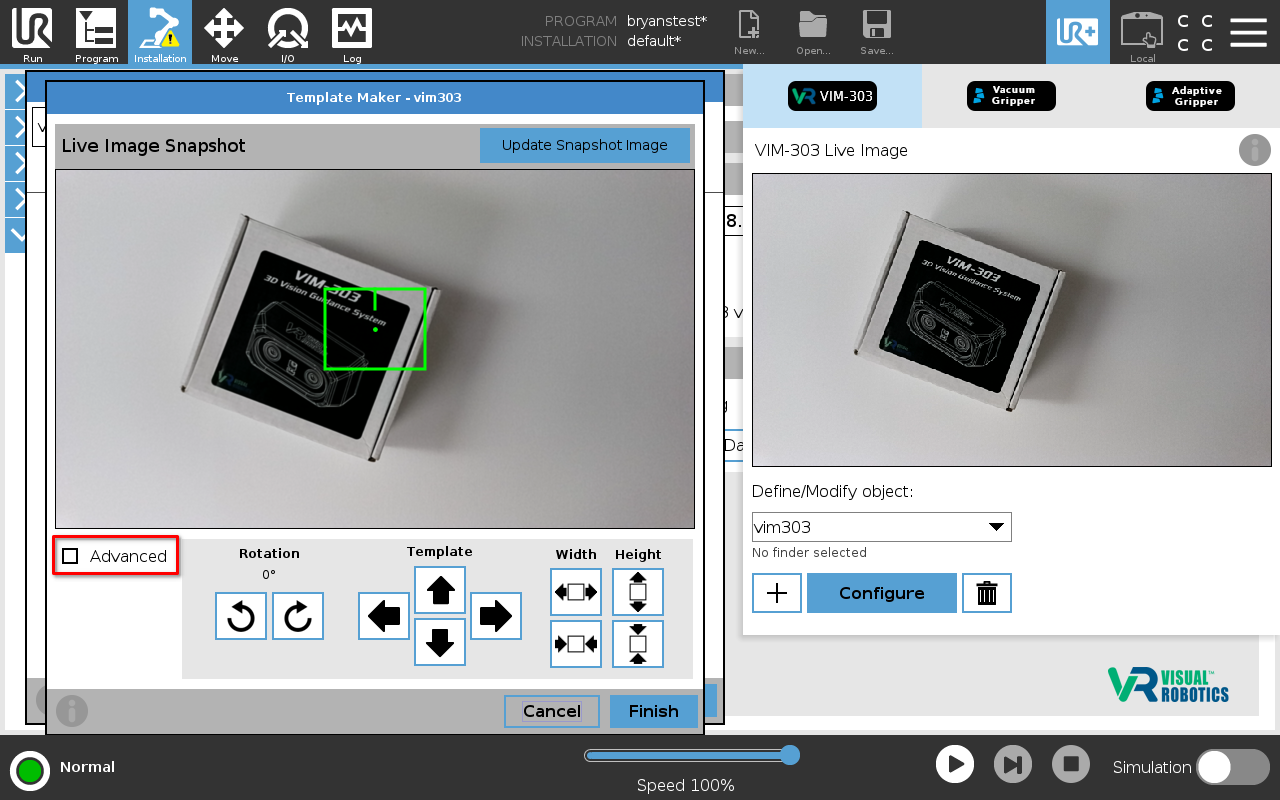
Figure 41: Template Maker Advanced mode
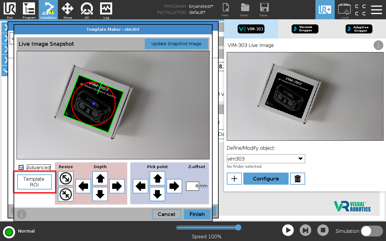
Figure 42: Template Maker in Advanced mode
The Red Circle represents the Depth ROI, which is used to determine the object’s height. The camera finds the average height of the objectwithin this ROI to know how far down to go to pick the object. Relevant values are set within the light red card. Use the left/right/up/down arrows to move the ROI circle and use the resize buttons to resize it. This can be used, for example, if the object’s top surface has a non-uniform height or has holes/cutouts/gaps.
The Blue Crosshair represents the Pick Point, which is an offset for where the camera picks the object. It is set relative to the center of the template ROI. It can be used, for example, if you want to pick from the corner of an object instead of the default middle. Relevant values are set within the light blue card. Use the left/right/up/down arrows to move the pick point. The Z-Offset is a custom offset in millimeters for the pick height, which is determined as the average height within the Depth ROI (red circle). Negative values offset upwards while positive values offset downwards. This adjustment can be used for fine tuning if the camera is picking too low or too high.
When Advanced mode is enabled, use the button below the Advanced checkbox (labeled either “Template ROI” or “Depth ROI Pick Point”) to toggle between movement of the advanced options and movement of the normal template ROI (green rectangle), as shown in Figure 41. The Advanced mode Template ROI page is shown in Figure 43 below.
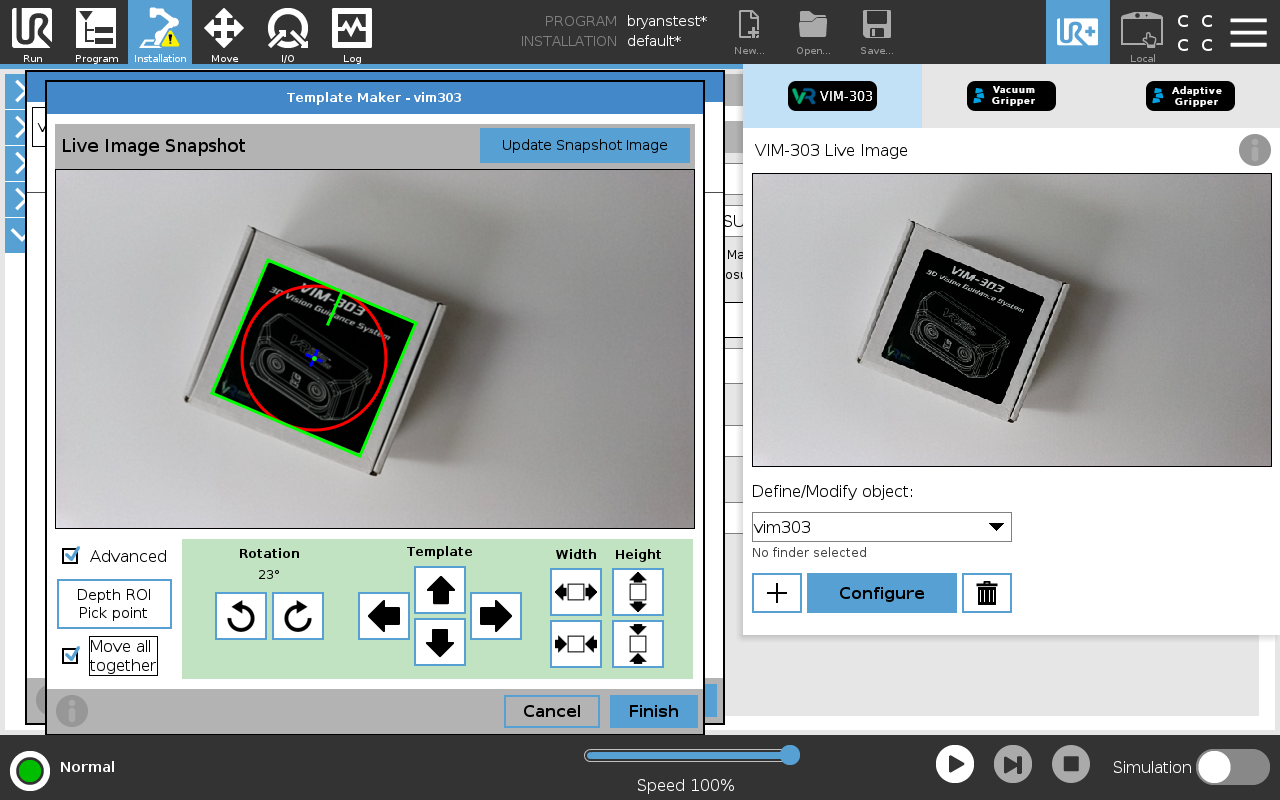
Figure 43: Template maker Advanced mode with Move all together
Also note that when in Advanced mode, an option called Move all together appears. When checked, all elements move together (template ROI, depth ROI, and pick point).
Figure 44 shows an example of a template object that benefits from the use of a custom Pick Point and Depth ROI. There is a hole in the middle of the object, and the height is not uniform.
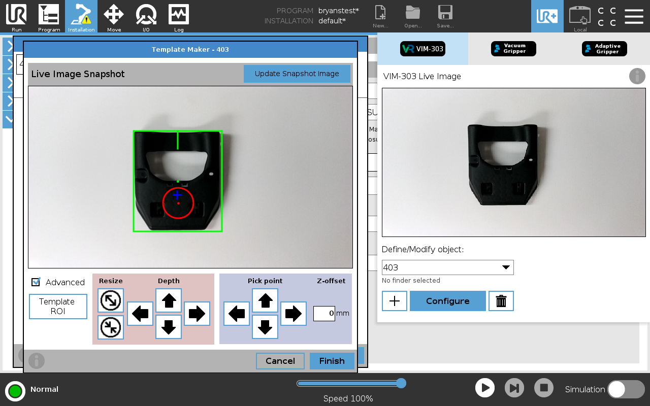
Figure 44: Template maker Advanced configuration example
Press Finish when all ROIs and points are aligned properly with the object as desired (Figure 44), resulting in the template image (Figure 40). When picking, the robot will move so that the end effector will be at the Pick Point, denoted by the blue crosshair. The robot will pick at the average height over the specified Depth ROI, denoted by the red circle, and offset by the Z-Offset value.
Setting Parameters and Training
As shown in Figure 45, set parameters of the Scale range, Angle range, Edge Threshold, and Feature Count in the Object Settings box, based on the desired scenario.
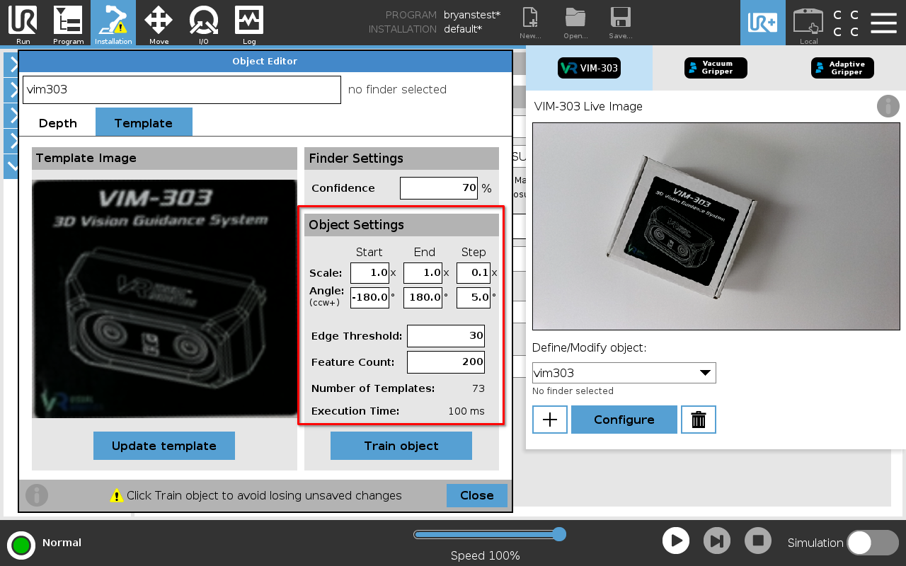
Figure 45: Template Parameters
A single Scale value of 1x is specified (1x start and 1x end), indicating the object will be seen at only 1x scale of when it was trained, or at the same distance.
The Angle range is from -180º to +180º in 5º increments. This allows the Template Finder to see this object at any orientation with respect to the camera.
The Edge Threshold and Feature Count are set to their default values.
The Number of Templates updates as the values of Scale range and Angle range are changed. In Figure 45, 73 templates will be created, covering a single scale with angles ranging from -180º to +180º in 5º increments.
When the Train object button is pressed, the camera starts the training process (Figure 46), which involves creating scaled and rotated copies of the template image and extracting the desired number of features from the template image. Depending on the number of templates being created, this could take a couple of seconds up to even a couple of minutes to complete. The total number of templates is limited to 1,200 per object, based on computational limitations.
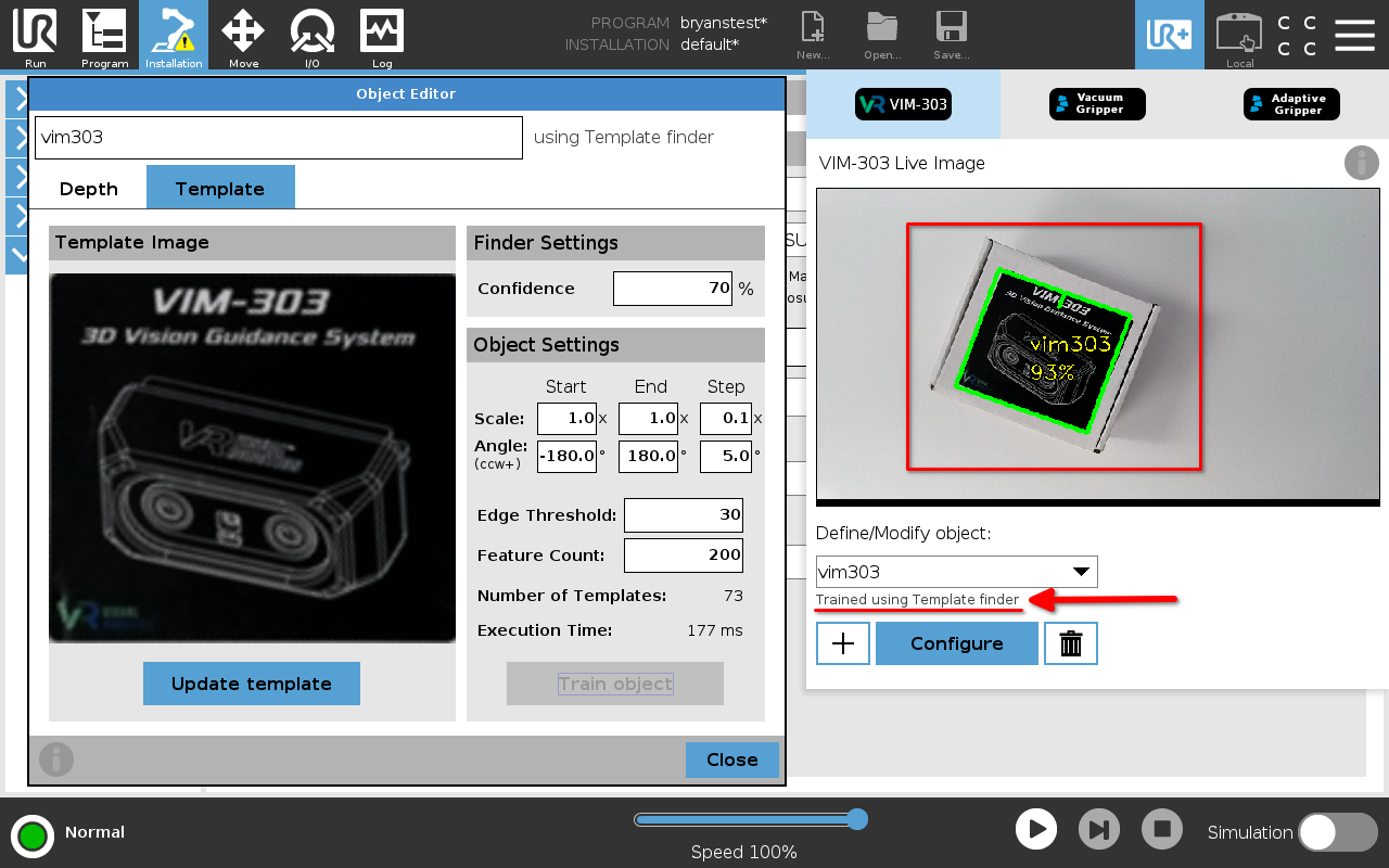
Figure 46: Template object trained
Once training is complete, the trained object will be shown in the live image window (Figure 46), and the Object Editor can be closed.
New objects can be trained by repeating this process. Multiple sides of an object can be trained by creating templates with different but ideally related names, if desired. Visual Pick and Visual Decide program nodes can be used to perform unique actions with different types of objects or different sides of the same object.
Verification
The object can be viewed in its environment within the same range of distances (due to scale factor) and rotation angles that match how the template was trained (Figure 47).
The object detection robustness can be verified using the UR+ menu (Figure 48). The Object Editor does not need to be active, but the Confidence can be conveniently adjusted from there. Setting it too low can result in spurious object detections. Setting it too high may prevent it from seeing objects on a complex background or if partially occluded.
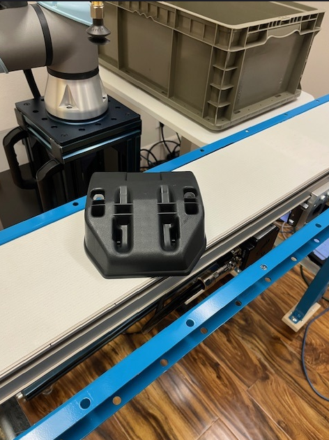
Figure 47: Object
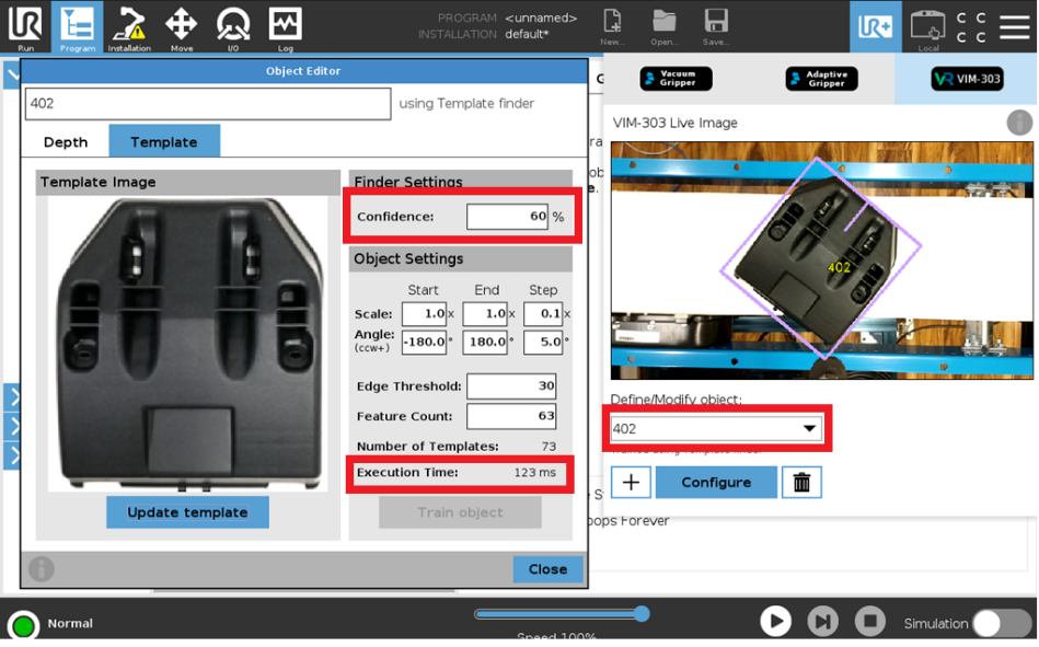
Figure 48: Detected Object
The object to be searched for can be changed from the pulldown menu on the UR+ menu (Figure 49). The Execution Time is shown for on the Object Editor for reference. The UR+ object selection pulldown only allows one type of object to be selected at a time, but through advanced settings in the Installation tab, multiple types of objects can be displayed (Figure 50).
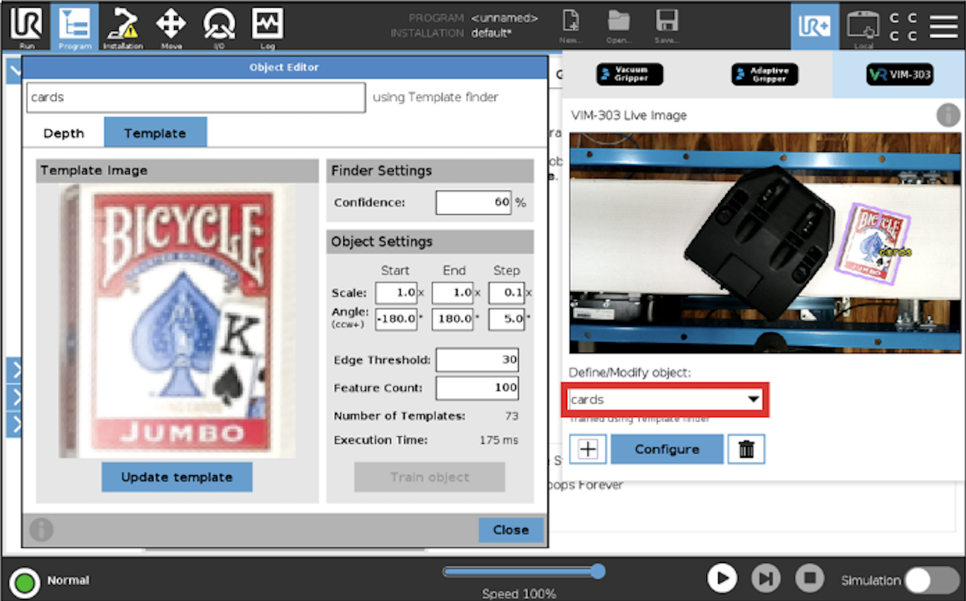
Figure 49: Different Object
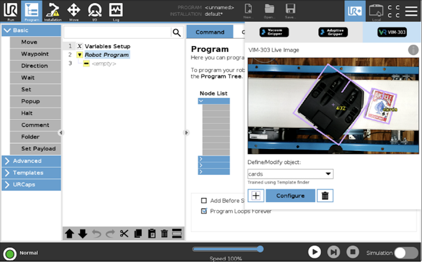
Figure 50: Multiple Objects
Debugging Object Detection with the Template Finder
Troubleshooting of the behavior of the Template Finder can be achieved through various settings in the Advanced menu on the Installation tab (Figure 51).
Please note that changing the selected object in the UR+ menu will in most cases revert changes made to these settings.
Edge Image
The Edge Image (Figure 51) can be shown by setting DEBUG_IMAGE:IMAGE_SOURCE = 6 (Template Finder) and setting TEMPLATE_FINDER:DEBUG_IMAGE_TYPE = 1 (Edges). This can be helpful to adjust the Edge Threshold parameter to see desirable edges and ignore subtle edges. The Object Editor can be opened (by pressing Configure on the UR+ menu) and the object could be trained with different Edge Threshold settings to find the correct value.
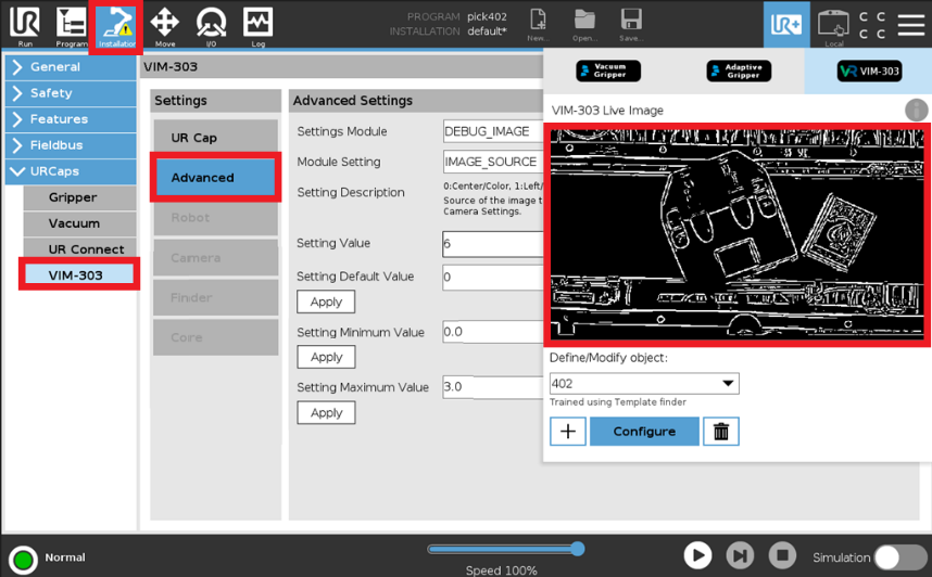
Figure 51: Edge Image
Template Features
Template features (Figure 52) can be shown by setting DEBUG_IMAGE:IMAGE_SOURCE = 6 (Template Finder) and setting TEMPLATE_FINDER:DEBUG_IMAGE_TYPE = 2 (Template). This shows features of the last trained object in the nominal orientation. Features (chosen edges) are shown in green. The Object Editor can be opened, and the object can be trained with different values of Feature Count in order to optimize the template to consider the desirable features.
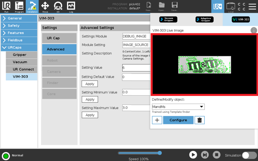
Figure 52: Template Features
When debugging is completed, set TEMPLATE_FINDER:DEBUG_IMAGE_TYPE = 0 (disable) to improve performance and set DEBUG_IMAGE:IMAGE_SOURCE = 0 (color) to revert to the default display of annotated objects on the color image.