
Configuring the VR Single Suction Gripper
The camera needs to know what end effector is connected to the robot and information about its TCP (Tool Center Position) and the camera’s TCP offset from the gripper. Follow these steps to configure the gripper.
-
Figure 16 shows the camera configuration required to use the Visual Robotics Single Suction Gripper.

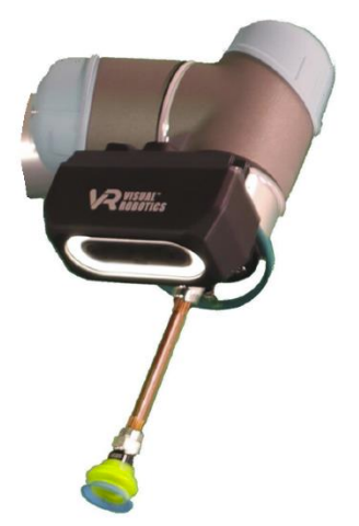
Figure 16: Visual Robotics Single Suction Gripper parameters
Settings result in a 5mm suction cup compression
-
In the Advanced tab in the VIM-303 installation tab, select the module ROBOT and setting GRIPPER and set it to the value from the appropriate gripper table in the VIM-303 Unboxing and Hardware Assembly Manual. For this example, the value from Figure 16 is used: “generic” (shown in Figure 17).
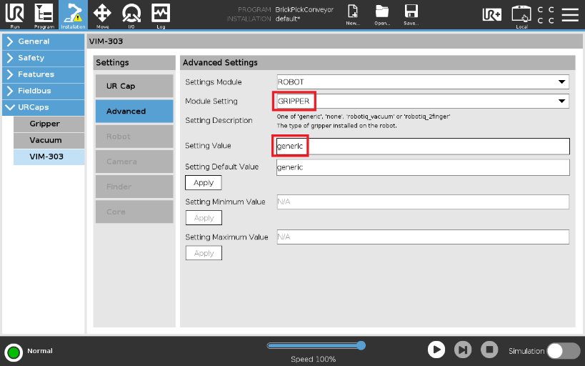
Figure 17: Set gripper type
-
Select the TCP_OFFSET setting in the ROBOT module and set according to the gripper table in Figure 17 (shown in Figure 19).
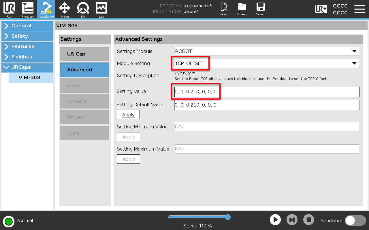
Figure 18: Set TCP offset
-
Select the TCP_CAMERA_OFFSET setting in the TRACKER module and set according to the gripper table in Figure 16 (shown in Figure 19). This is the offset from the end-effector TCP to the front surface of the camera along the optical axis of the right stereo camera.
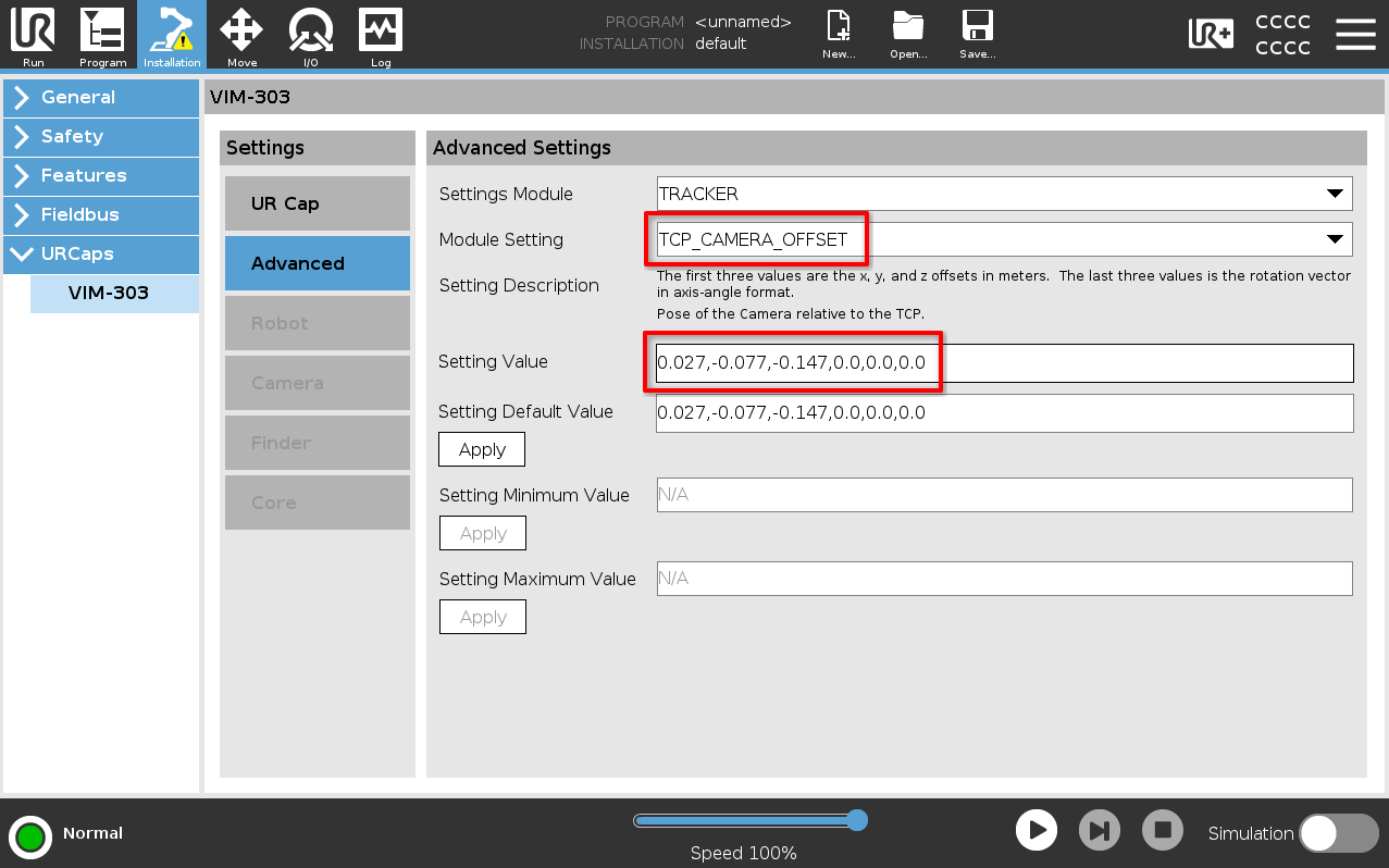
Figure 19: Set TCP camera offset
-
Set the Robot’s TCP to the same value as the TCP offset from step 3 (Figure 20). Note that the Robot TCP is entered in millimeters for the robot and in meters in the camera. The camera and the robot need to agree on the robot’s TCP setting.
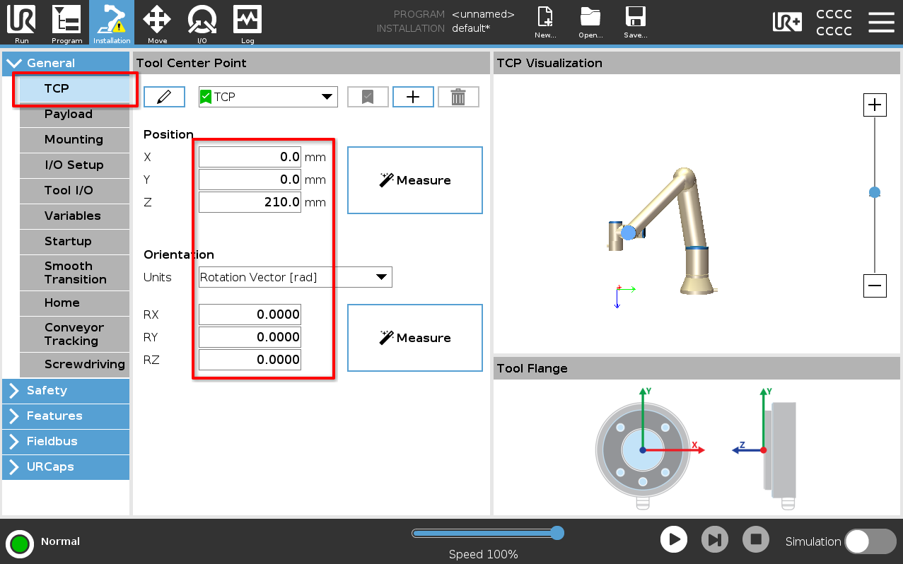
Figure 20: Set Robot's TCP