
Mounting VR Single Suction Gripper
Kit Contents
Figure 5 shows the Visual Robotics gripper kit components. Figure 6 shows the Mount and the suction end effector from the gripper kit.
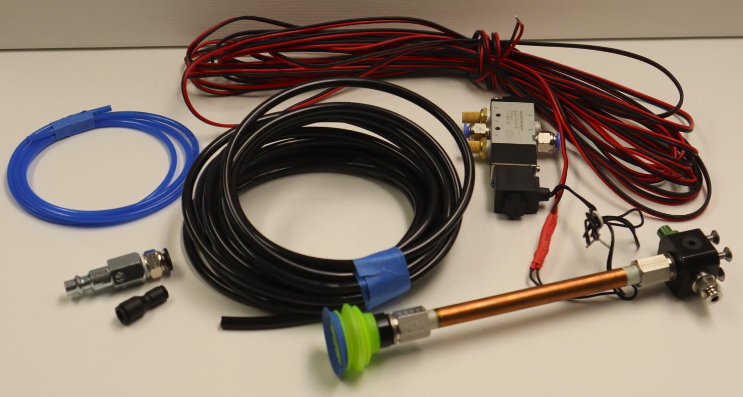
Figure 5: Visual Robotics Suction Gripper Kit Components
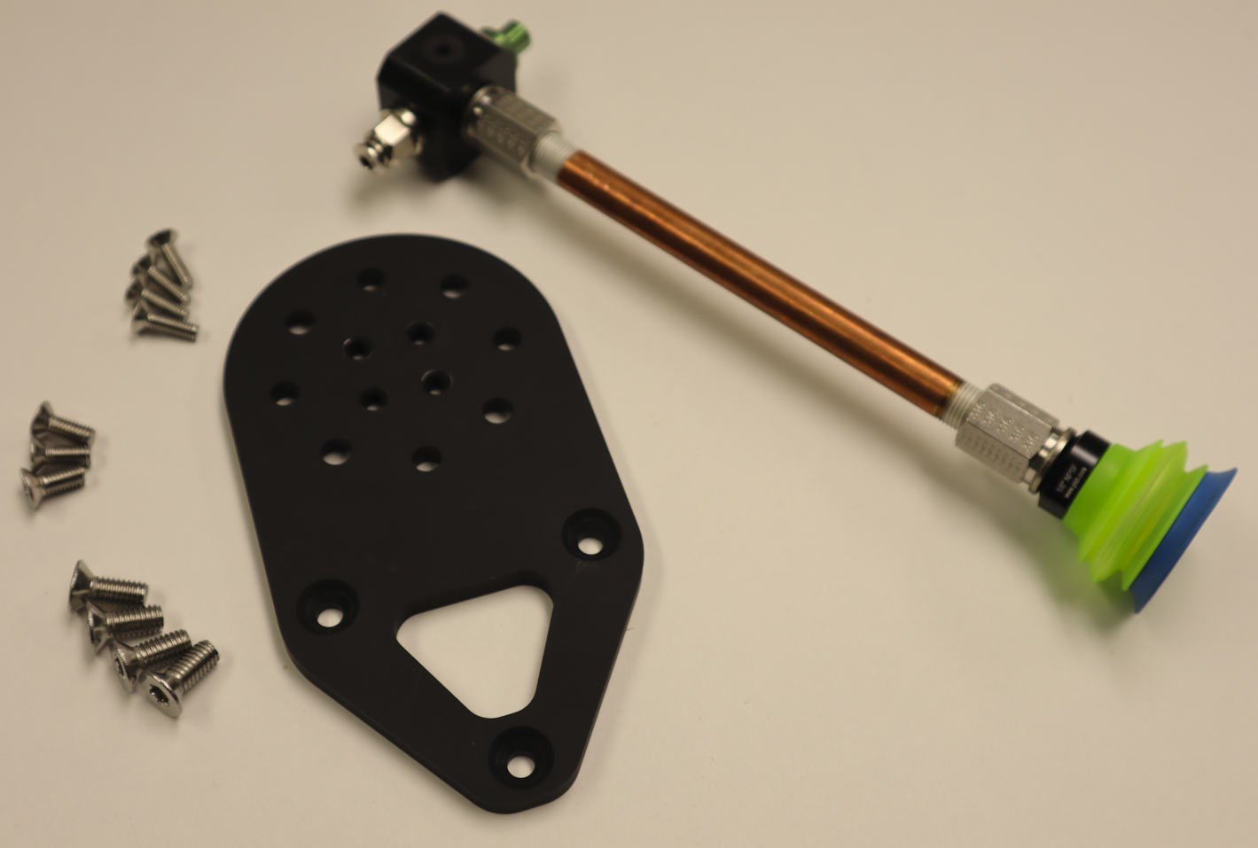
Figure 6: Mount and Suction End Effector
Assemble the suction end effector to the mount (Figure 7), ensuring that the green exhaust port faces toward the triangular face of the mount and the gripper is on the side of the mount with the circular ridge. The end effector is fastened to the mount with the four included M4 flathead screws (Figure 8). Attach the mount assembly to the wrist of a Universal Robots UR3, UR5, or UR10, ensuring that the triangle shape of the mount (where the camera will be mounted) is aimed in the same direction as the wrist connector using the four included M6 screws (Figure 9).
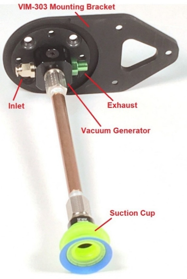
Figure 7: Assembling Gripper to Mount
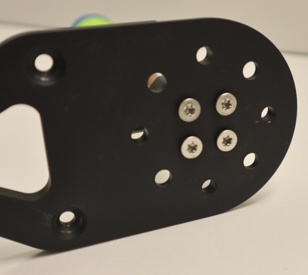
Figure 8: Gripper Mounting Screws
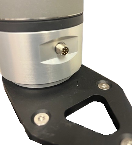
Figure 9: Orientation for Mounting on Robot Wrist
Assembling the Pneumatic Valve
Connect the wires from the valve to DO0 and 0V on the Universal Robots controller (Figure 10). Polarity isn’t critical, but for convention hook the black wire to 0V.
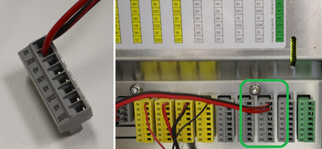
Figure 10: Electrical Connection of Valve to Universal Robots Controller
Cut the black 6mm tubing to length as desired and connect the air inlet tubing to port P and the controlled air outlet to the gripper to B (Figure 11).
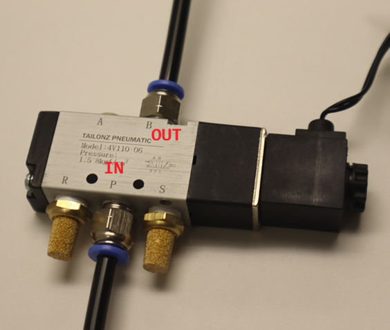
Figure 11: Pneumatic Hose Connections to Valve
Attach the compressor coupling to the tubing connected to port P (Figure 12) and connect the 6mm to 4mm adapter to the tubing connected to port B (Figure 13). Connect the 4mm tubing to the gripper (Figure 14).
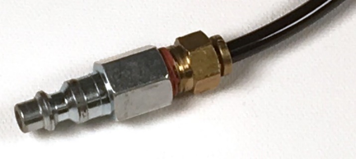
Figure 12: Compressor Connection
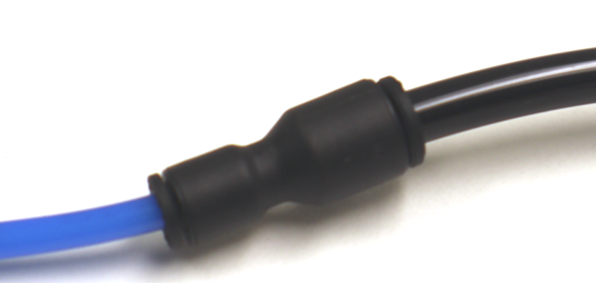
Figure 13: 6mm to 4mm adapter
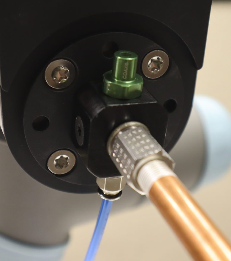
Figure 14: 4mm Tubing Connection to Gripper
Assembling the Camera to the Mount and Attaching the Cable
Attach the camera onto the mount using the three included M5 screws (Figure 15). Loosely place the screws first and then tighten in order to maximize the mounting accuracy. Carefully screw the Ethernet cable into the camera with the cable oriented as shown (Figure 15).
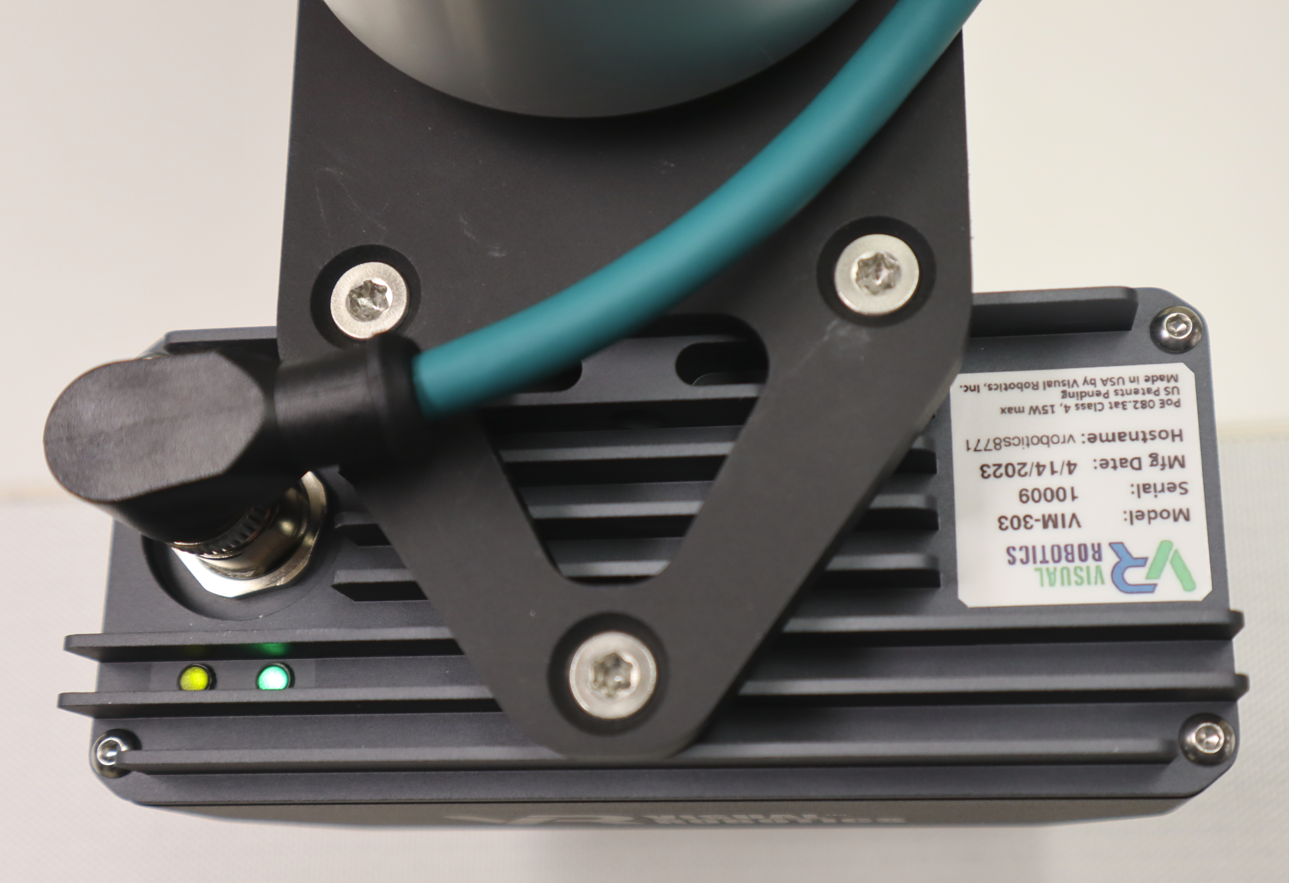
Figure 15: Camera Attachment to Mount and Cable Orientation