
Mounting Additional Grippers
This page will cover how to mount the Visual Robotics Quad gripper, Robotiq E-Pick Single Suction Gripper, and the Robotiq 2F-85 Two Finger Gripper. If you only need to mount the Visual Robotics Single Suction Gripper, please refer to the Mounting VR Single Suction Gripper page. If you have already completed those steps, you can skip to the Electrical Connections page.
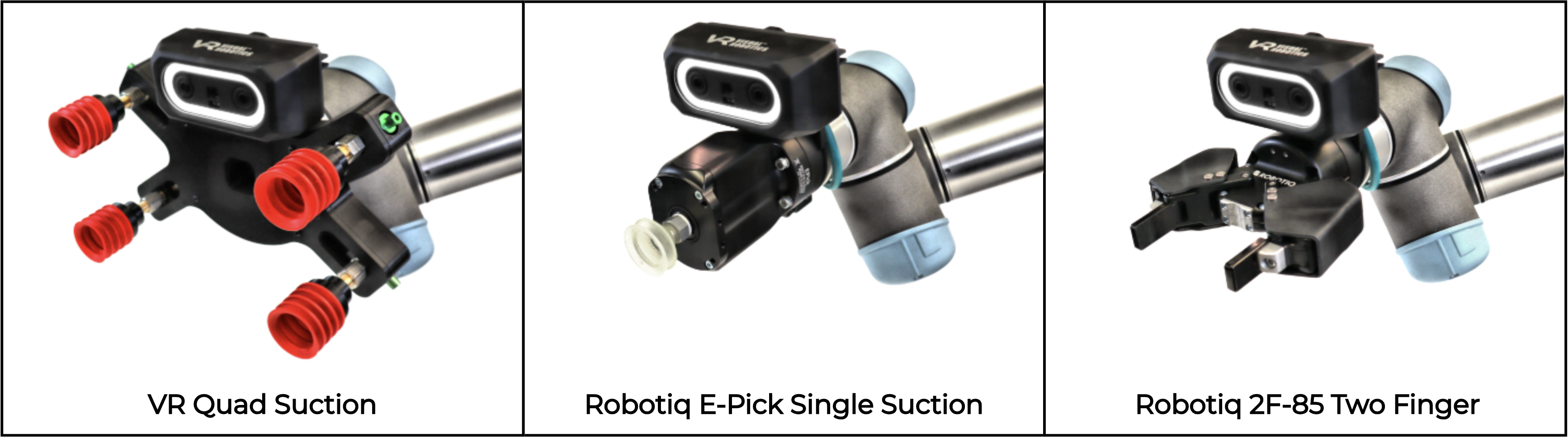
Visual Robotics Quad Gripper
Kit Contents
Figure 16 shows the Visual Robotics Quad gripper kit components. Figure 17 shows the Camera Mount and screws.
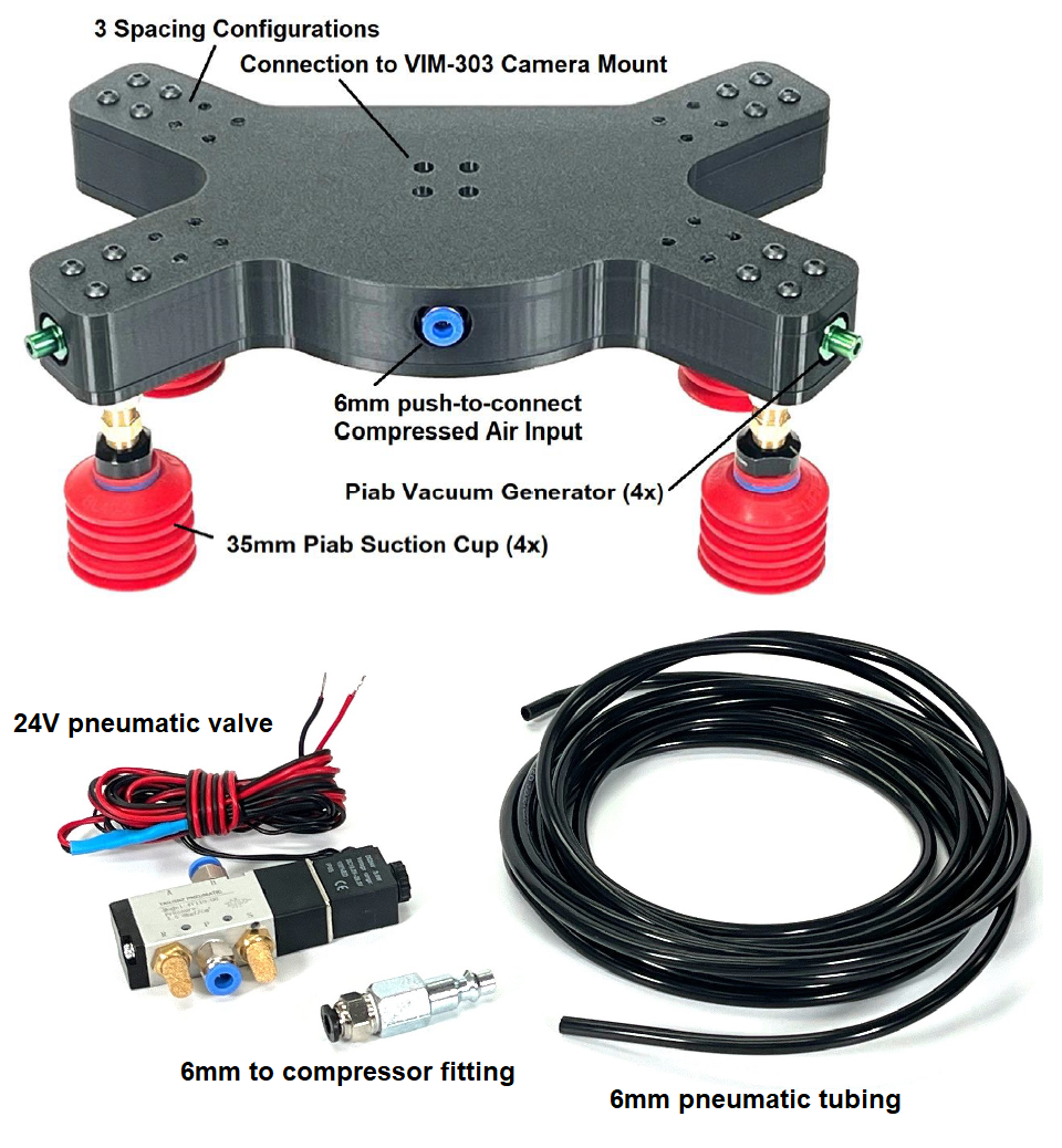
Figure 16: Visual Robotics Quad Suction Gripper Kit Components
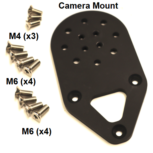
Figure 17: Mount and Screws
Assemble the Camera Mount to the robot with 4 M6 screws (Figure 18), ensuring that the wrist connector is aimed in the same direction of the triangular section of the plate that holds the camera.
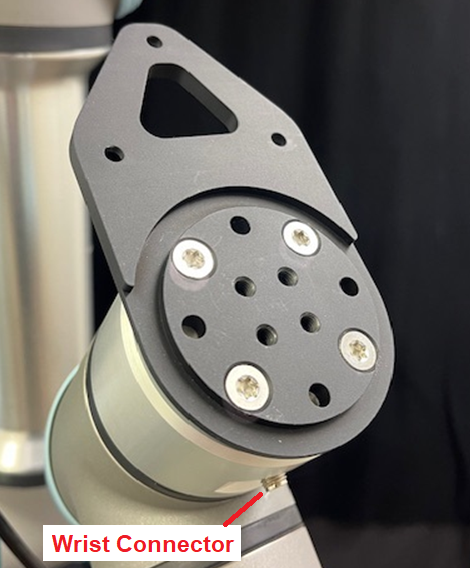
Figure 18: Assembling Camera Mount to the Robot
Assembling the Camera to the Mount and Attaching the Cable
Attach the camera onto the mount using the three included M5 screws (Figure 19). Loosely place the screws in first and then tighten in order to maximize the mounting accuracy. Carefully screw the Ethernet cable into the camera with the cable oriented as shown (Figure 19).
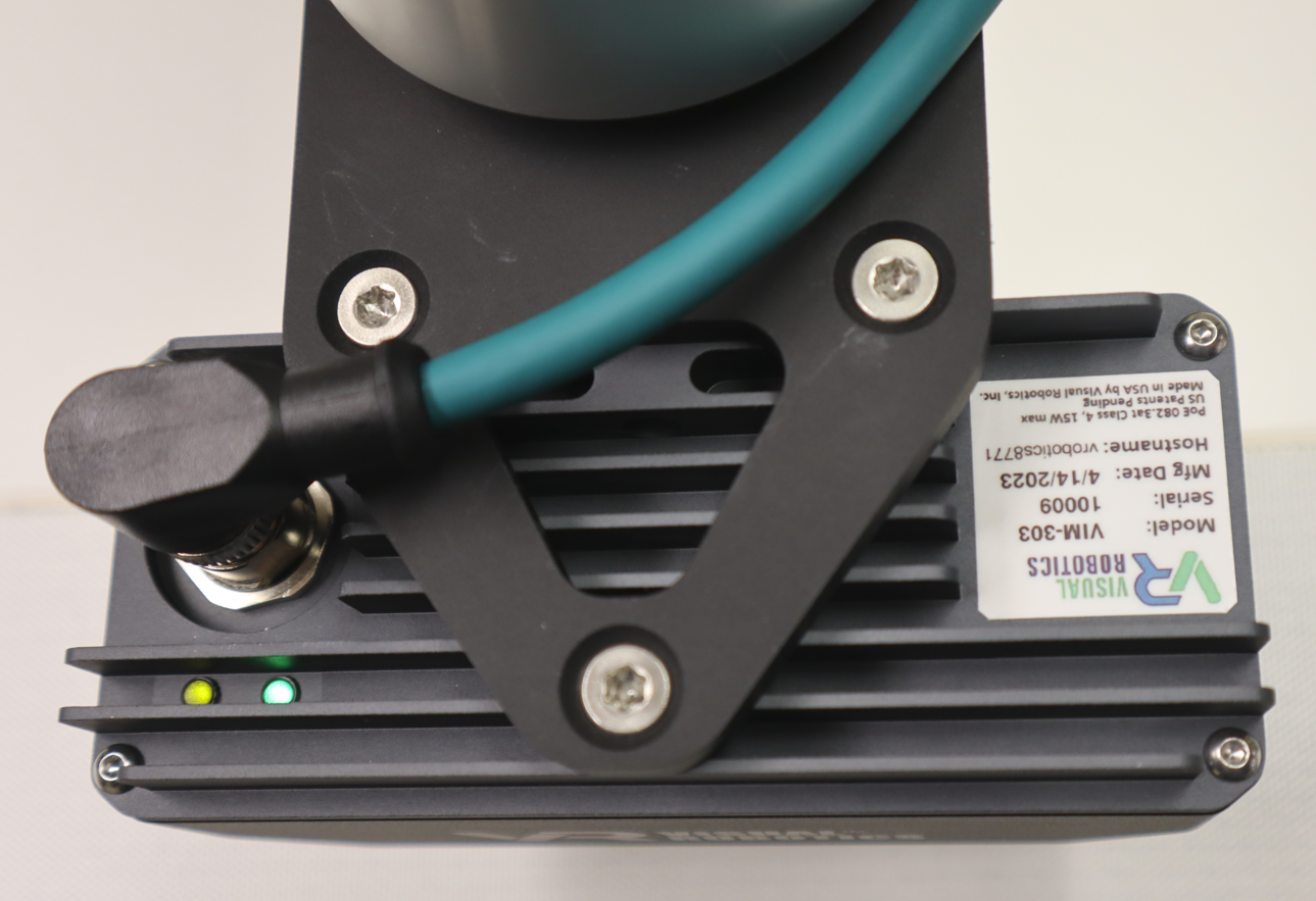
Figure 19: Camera Attachment to Mount and Cable Orientation
Assembling the Pneumatic Valve
Connect the wires from the valve to DO0 and 0V on the Universal Robots controller (Figure 20). Polarity isn’t critical, but for convention hook the black wire to 0V. It may be convenient to house the valve inside the Univeral Robots Controller box. The air inlet from the compressor goes to port P. The air outlet to the gripper goes to port B (Figure 21). Cut the black 6mm tubing to length as desired. Attach the compressor coupling to the tubing connected to port P (Figure 22).
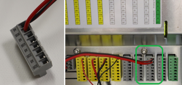
Figure 20: Electrical Connection of Valve to Universal Robots Controller
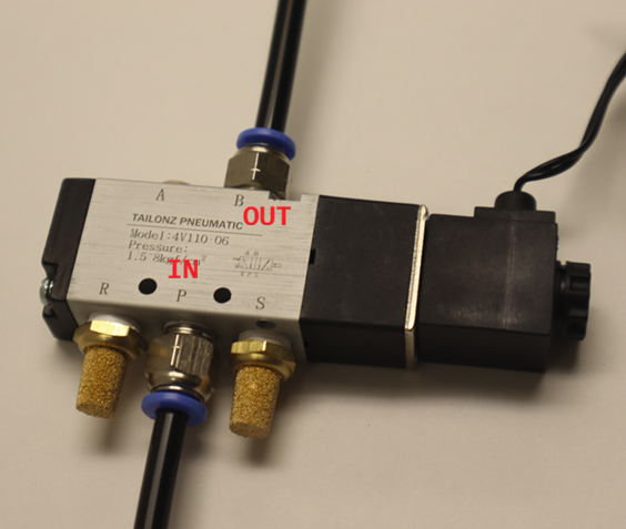
Figure 21: Pneumatic Hose Connections to Valve
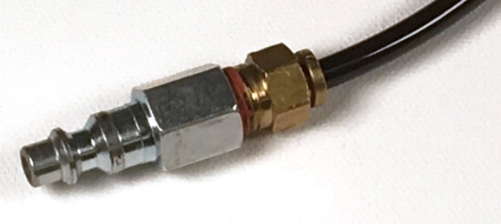
Figure 22: Compressor Connection
Assembling the Gripper to the Camera Mount
With the camera oriented on the robot as shown in Figure 23, mount the Quad Gripper to the Camera Mount using 4 M6 screws as shown in Figure 24. Stifle a grin as you ponder its anthromorphic shape. Attach the 6mm tubing from valve port B to the gripper as shown in Figure 25. The completed assembly is shown in Figure 26.
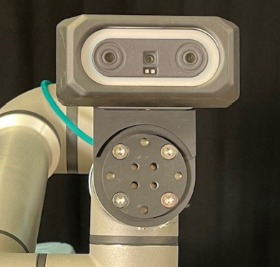
Figure 23: Camera Orientation
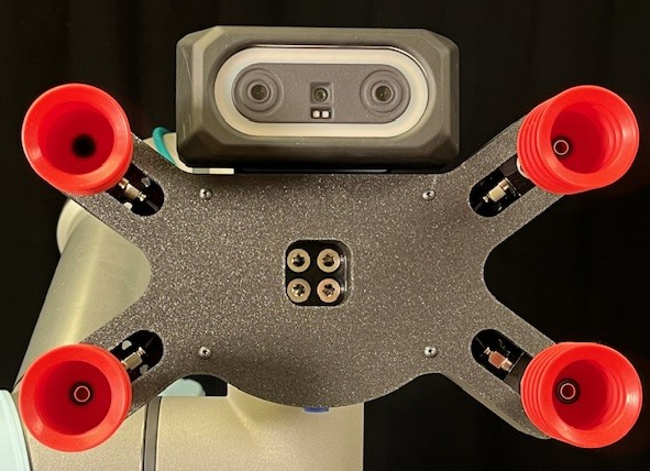
Figure 24: Mounting of Quad Gripper
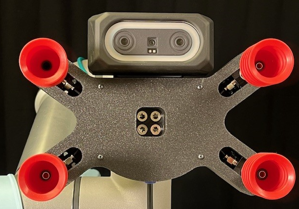
Figure 25: Attaching 6mm pneumatic tubing to Gripper
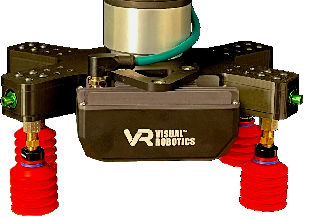
Figure 26: Quad Gripper mounted to Robot
Robotiq E-Pick Single Suction Gripper
Kit Contents
Figure 27 shows the components for the Robotq E-Pick Suction Gripper Kit. The Robotiq Coupling Interface and Robotiq E-Pick Gripper are manufactured by Robotiq. The VIM-303 Mounting Bracket and screws are provided by Visual Robotics. Figure 27 is shown for the Universal Robots e-Series. Cable attachment for the Universal Robots CB-Series is different, described in the CB-Series section at the end.
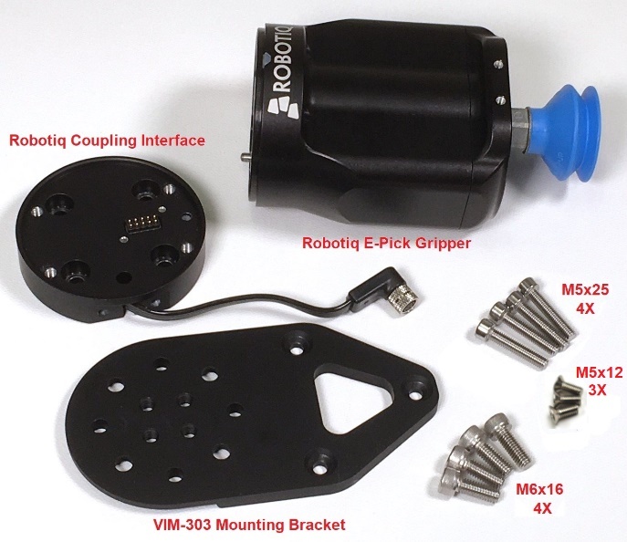
Figure 27: Robotiq E-Pick Suction Gripper Kit components
Attaching VIM-303 Mounting Bracket and Robotiq Coupling Interface
As shown in Figure 28, place the VIM-303 Mounting Bracket with the circular ridge side away from the robot’s wrist and with the triangular portion aimed in the same direction of the wrist connector. Place the Robotiq Coupling Interface on top of the VIM-303 Mounting Bracket and orient its cable so it points toward the wrist connector. The contact pins of the Coupling Interface should be oriented as shown in Figure 28. Screw the Coupling Interface and Mounting Bracket into the robot’s wrist using the four M6x16 screws. Loosely place the screws in first and then tighten in a diagonal pattern in order to maximize the mounting accuracy
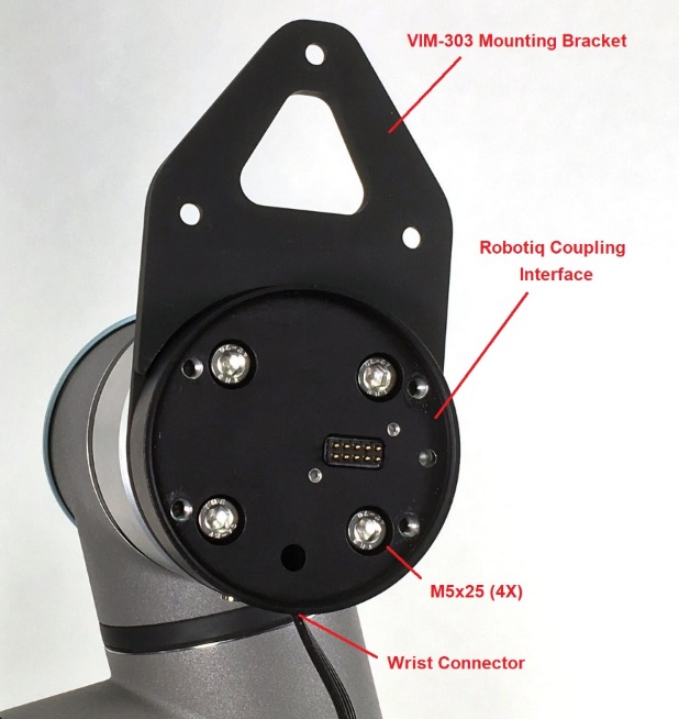
Figure 28: Attaching VIM-303 Mounting Bracket and Robotiq Coupling Interface
Attaching the Robotiq E-Pick Gripper
As shown in Figure 29, attach the Robotiq E-Pick Gripper to the Robotiq Coupling Interface using the four M5x25 screws, ensuring that the gripper contacts are oriented properly with respect to the Robotiq Coupling Interface contacts. Loosely place the screws in first and then tighten in a diagonal pattern in order to maximize the mounting accuracy.
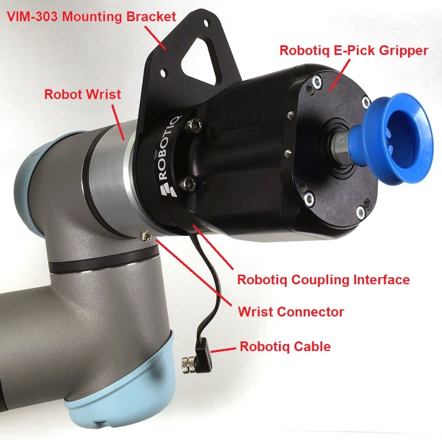
Figure 29: Attaching the Robotiq E-Pick Gripper
Attaching the VIM-303 Camera
Attach the camera onto the mount using the three included M5x12 screws (Figure 30). Loosely place the screws in first and then tighten in order to maximize the mounting accuracy.
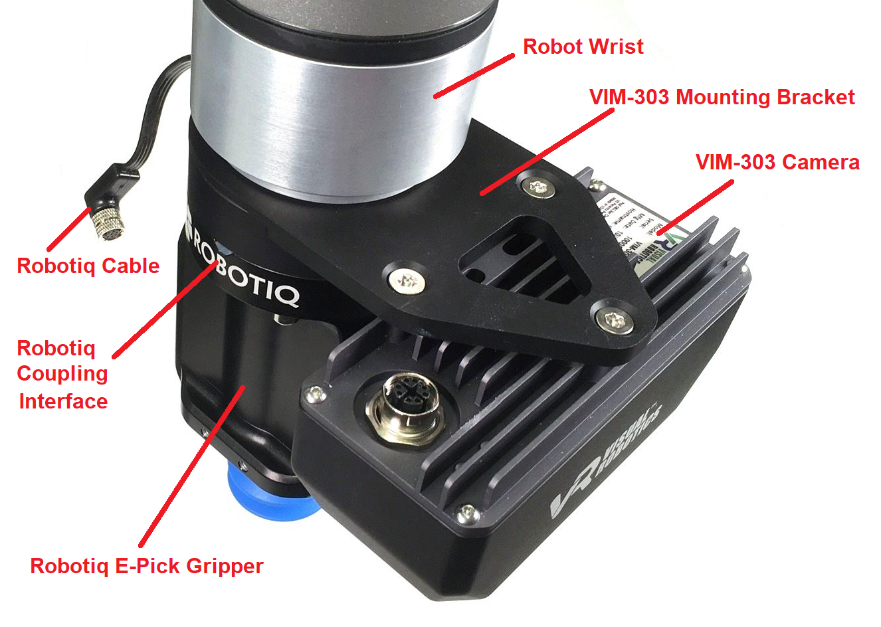
Figure 30: Attaching VIM-303 Camera
Attaching the Cables
Carefully screw the Ethernet cable into the camera with the cable oriented as shown (Figure 31). Attach the Robotiq Cable to the robot wrist connector as shown (Figure 31). Robotiq cable will plug in on the front side not the back with the preferred orientation arrangement (opposite of what is shown in Figure 31) to enable increased wrist rotation range.
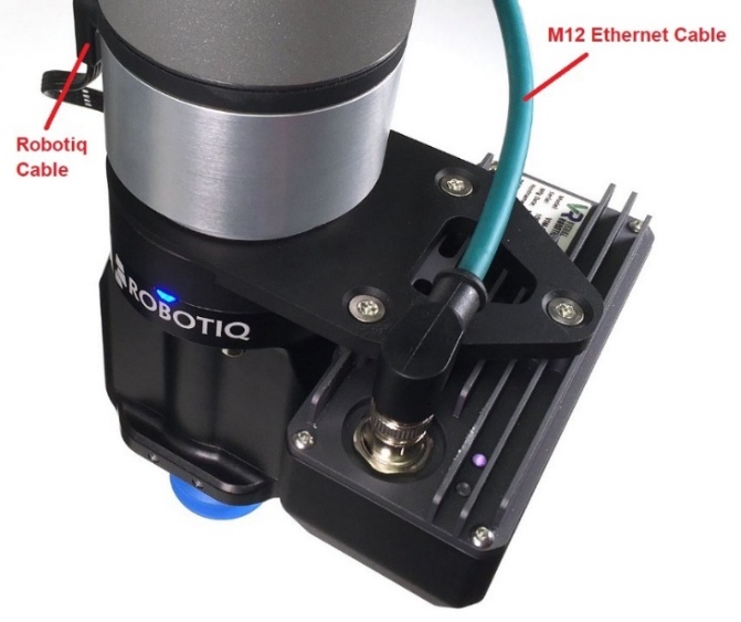
Figure 31: Attaching the Cables
Universal Robots CB-Series
The Universal Robots CB-Series does not provide digital communication to the wrist. A different Robotiq Coupling Interface is required to connect the gripper to a CB-Series robot (Figure 32). Attach this Coupling Interface so that the contact pins are oriented with respect to the robot wrist as shown in Figure 28. The cable will be sticking out the side instead of downward. Follow the rest of the steps through the step of attaching the Ethernet cable to the VIM-303 camera. Attach the Robotiq extension cable to the Coupling Interface cable and connect it to the Robotiq Communication Adapter (Figure 33) as directed in the Robotiq manual
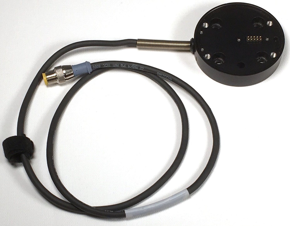
Figure 32: CB Series Robotiq Coupling Interface
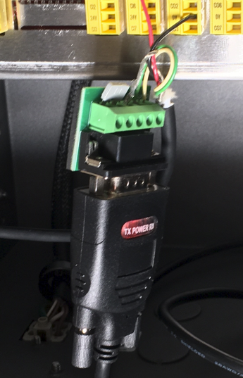
Figure 33: Robotiq Communication Adapter
Robotiq 2F-85 and 2F-140 Two Finger Grippers
Kit Cntents
Figure 34 shows the components for the Robotq 2F-85 or 2F-140 Two Finger Gripper Kit. The Robotiq Coupling Interface and Robotiq 2F-85 and 2F-140 Grippers are manufactured by Robotiq. The VIM-303 Mounting Bracket and screws are provided by Visual Robotics. Figure 34 is shown for the Universal Robots e-Series. Cable attachment for the Universal Robots CB-Series is different, described in the CB-Series section at the end.
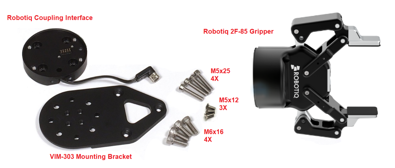
Figure 34: Robotiq 2 Finger Gripper Kit components
Attaching VIM-303 Mounting Bracket and Robotiq Coupling Interface
As shown in Figure 35, place the VIM-303 Mounting Bracket with the circular ridge side away from the robot’s wrist and with the triangular portion aimed in the same direction of the wrist connector. Place the Robotiq Coupling Interface on top of the VIM-303 Mounting Bracket and orient its cable so it points toward the wrist connector. The contact pins of the Coupling Interface should be oriented as shown in Figure 35. Screw the Coupling Interface and Mounting Bracket into the robot’s wrist using the four M6x16 screws. Loosely place the screws in first and then tighten in a diagonal pattern in order to maximize the mounting accuracy
Figure 35: Attaching VIM-303 Mounting Bracket and Robotiq Coupling Interface
Attaching the Robotiq 2F-85 or 2F-140 Two Finger Gripper
As shown in Figure 36, attach the Robotiq 2F-85 or 2F-140 Two Finger Gripper to the Robotiq Coupling Interface using the four M5x25 screws, ensuring that the gripper contacts are oriented properly with respect to the Robotiq Coupling Interface contacts. Loosely place the screws in first and then tighten in a diagonal pattern in order to maximize the mounting accuracy.
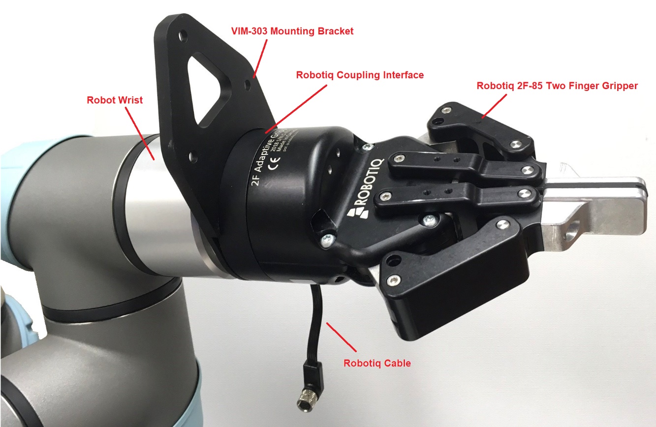
Figure 36: Attaching the Robotiq 2F-85 (or 2F-140) Two Finger Gripper
Attaching the VIM-303 Camera
Attach the camera onto the mount using the three included M5x12 screws (Figure 37). Loosely place the screws in first and then tighten in order to maximize the mounting accuracy.
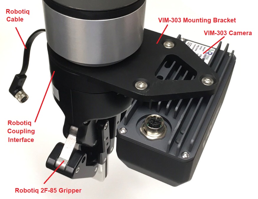
Figure 37: Attaching the VIM-303 Camera
Attaching the Cables
Carefully screw the Ethernet cable into the camera with the cable oriented as shown (Figure 38). Attach the Robotiq Cable to the robot wrist connector as shown (Figure 38). Robotiq cable will actually connect on the front side by the camera with the preferred mounting arrangement (opposite of what is shown).
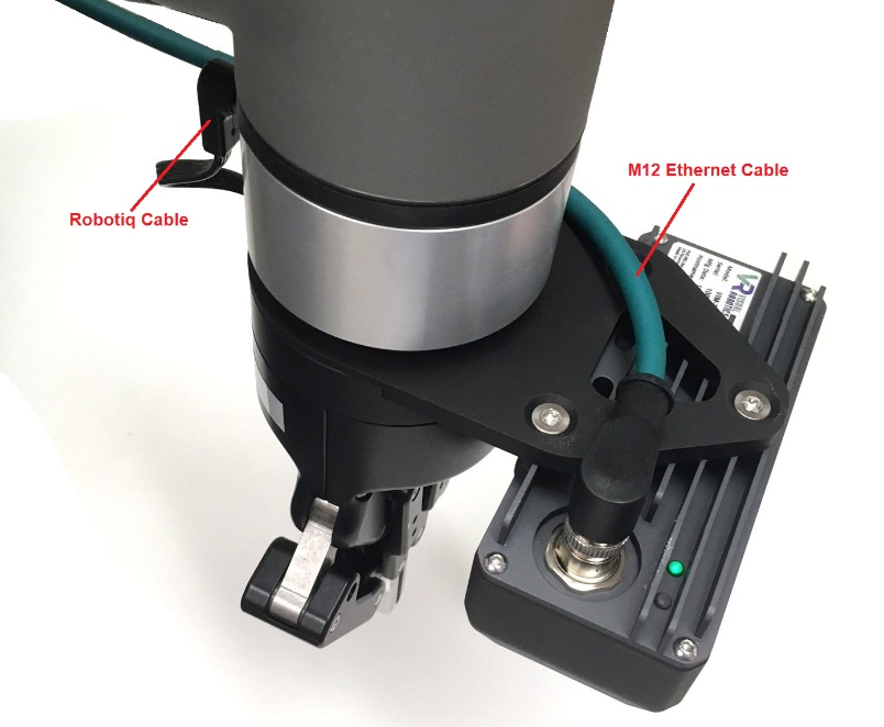
Figure 38: Attaching Cables
Universal Robots CB-Series
The Universal Robots CB-Series does not provide digital communication to the wrist. A different Robotiq Coupling Interface is required to connect the gripper to a CB-Series robot (Figure 39). Attach this Coupling Interface so that the contact pins are oriented with respect to the robot wrist as shown in Figure 35. The cable will be sticking out the side instead of downward. Follow the rest of the steps through the step of attaching the Ethernet cable to the VIM-303 camera. Attach the Robotiq extension cable to the Coupling Interface cable and connect it to the Robotiq Communication Adapter (Figure 40) as directed in the Robotiq manual
Figure 39: CB Series Robotiq Coupling Interface
Figure 40: Robotiq Communication Adapter