Configuring (Programming) Tasks
To create a new task or modify the behavior of an existing task, the Programmer presses the Configure gear from the task menu (Figure 9). The Programmer is presented with several tabs (Figure 10) including Workspaces, Objects, Waypoints, Blockly, Camera, Advanced, and Tasks, which will each be described further in this manual.
Returning to the Task Menu when the Programmer has completed the creation of new tasks, is accomplished by pressing the Task Menu button (home icon), allowing the operator to execute tasks with the workcell.
Administrative tasks, such as viewing logs of the system behavior, network administration, and updating firmware, are accessed by pressing the Admin button (padlock icon).
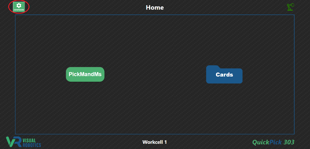
Figure 9: Configuring (Programming) tasks
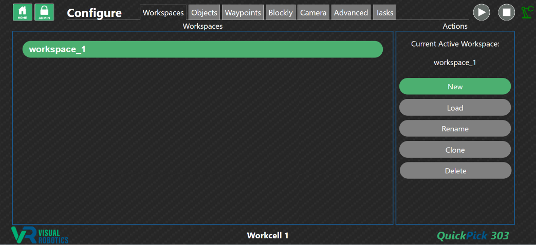
Figure 10: Configure (Programming) Tabs
Workspaces Tab
Workspaces are switchable environments containing unique Objects, Waypoints, Blockly tasks (programs), and Settings. It is often convenient for multiple Blockly tasks to share common Objects, Waypoints, and Settings. These tasks should reside in the same Workspace. However, it may be beneficial to create a new Workspace, in order to have a different set of Objects, redefine the location of Waypoints with the same name, or use different settings (for the camera, gripper, etc.).
The Workspaces tab (Figure 11) allows the Programmer to manage Workspaces. A camera fresh from the factory will have one Workspace defined: workspace_1. New Workspaces can be created by pressing the New button (Figure 12), and will create a new Workspace with no Objects, no Waypoints, no Blockly tasks, and factory default settings.
Figure 11: Workspaces Tab
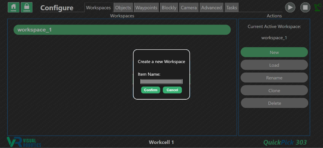
Figure 12: Creating a New Workspace
Figure 13 shows two Workspaces. The active Workspace (for example workspace_1) is indicated in green, and other Workspaces are indicated in blue. Single clicking on a Workspace selects it (shown as outlined in white) for modification but does not make it active.
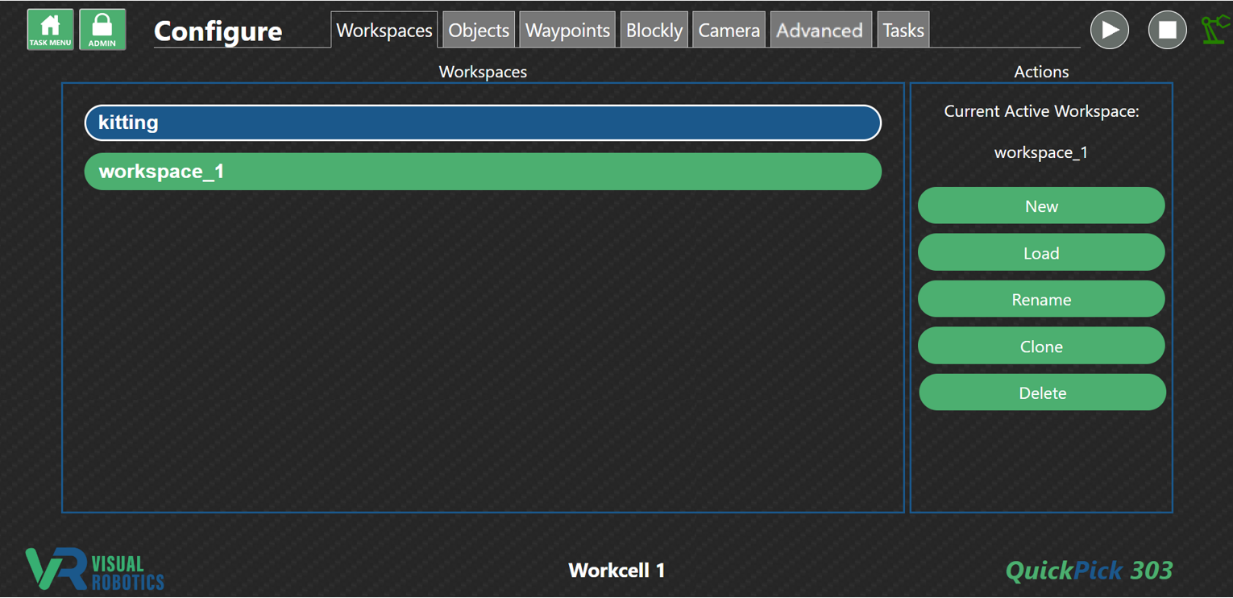
Figure 13: Selecting a Workspace
Double clicking or selecting and pressing the Load button on a Workspace will make it active. All of the Objects, Waypoints, Blockly tasks, and Settings will be loaded.
Rename a Workspace by selecting it and pressing the Rename button.
A copy (clone) of a Workspace can be created by selecting the Workspace and pressing the Clone button. This may be useful to create a copy of another Workspace’s Objects, Waypoints, Blockly tasks, and Settings as a starting point and then change them for a specific purpose.
A Workspace that is not active can be deleted by selecting it and pressing the Delete button. The active Workspace cannot be deleted. There must be at least one Workspace.
Objects Tab
The Objects tab currently only supports modification of depth objects. Template objects can be created and interfaced with in the UR Cap.
The Objects tab is used to define objects for the VIM-303 camera to interface with (Figure 14). Objects are detected using the Depth Finder, which measures the dimensions and 3D location of prismatic objects (objects that have a flat-top surface) on a flat surface. The surface is assumed to be normal (at right angles to) the camera’s optical axis (direction that the camera is pointing). The depth from the front of the camera to this surface is set by the slider when the Surface Height is set to Manual and is automatically calculated (based on the median depth of what the camera sees) when the slider is set to Auto. Depending on the annotation settings, the object of interest will be outlined in purple.
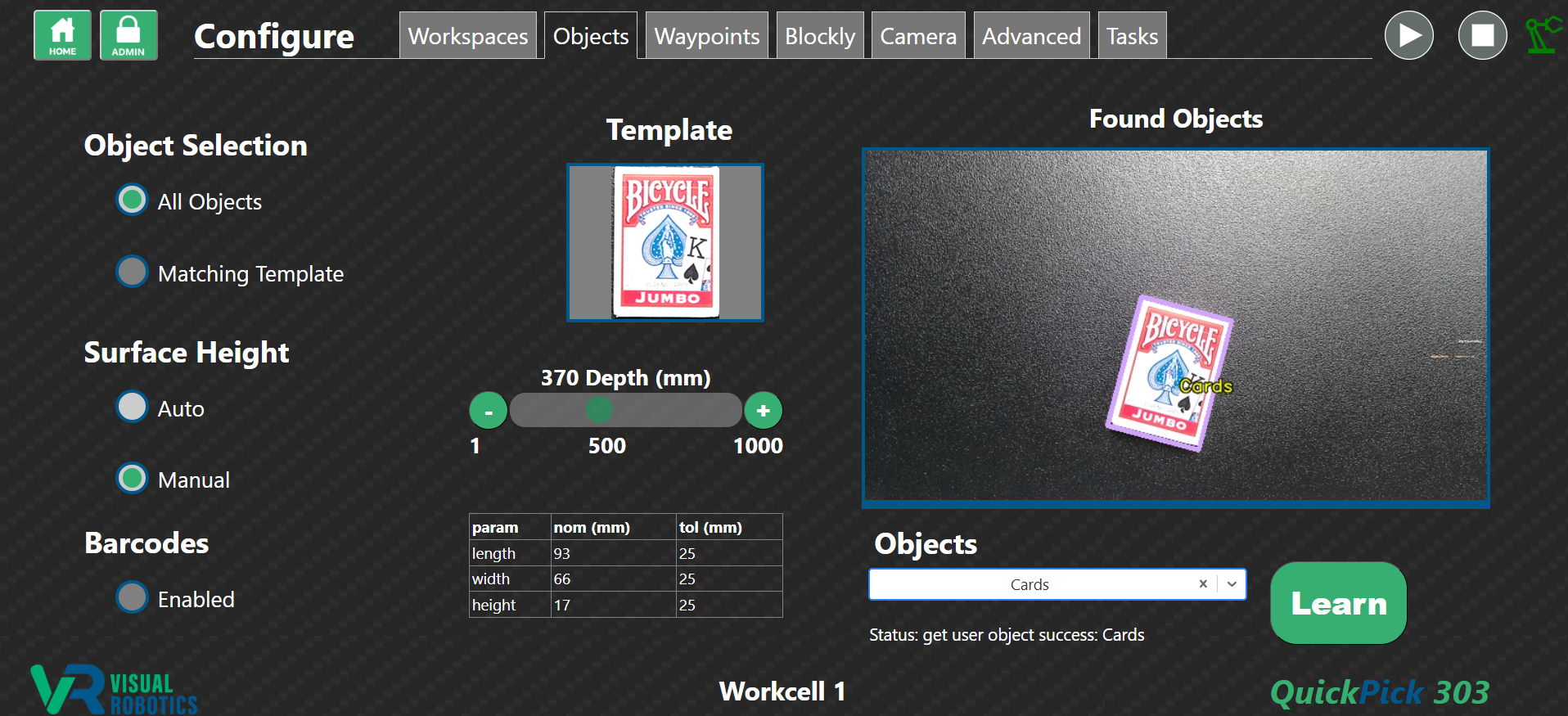
Figure 14: Objects Tab
To train a new depth object, ensure that only one object is in the field of view of the camera. The object should be outlined in purple and may be labeled as Unknown if the camera has never been taught this object before (Figure 15). Type the name of the object in the Objects pulldown menu. Press Create when prompted. The object’s label should change to match the name that was defined (Figure 16). The dimensions should match that of the object. A thumbnail image is captured at the time of training, for visual reference of the object that has been trained.
An existing object can be retrained by placing a single copy of the object in the field of view, selecting the object name from the menu and pressing Learn. The template image and dimensions will be updated accordingly.
In this version of firmware, Object Selection of Matching Template and Barcodes Enabled both have no effect. These buttons are placeholders for future software versions that support Template Matching and Barcode reading.
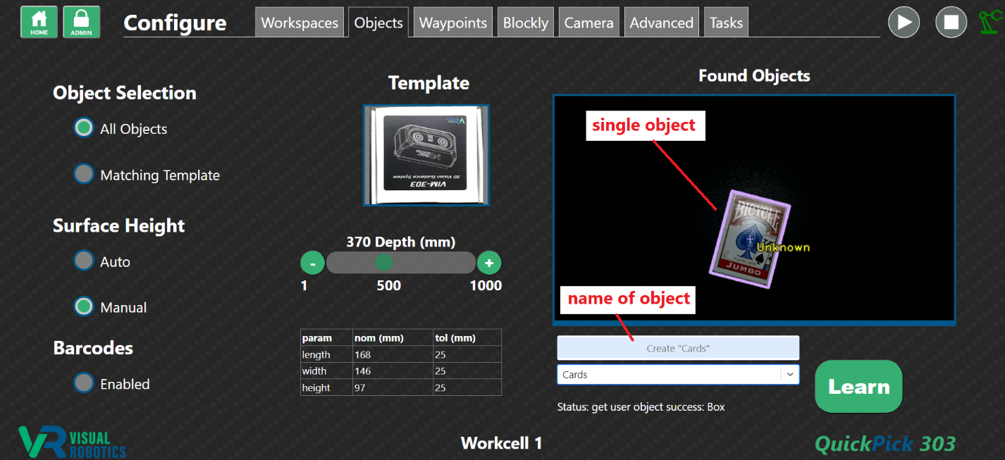
Figure 15: Create a new Object
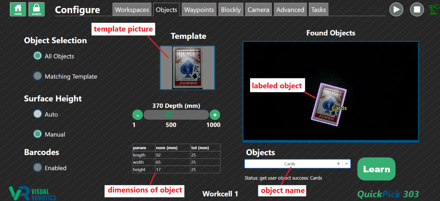
Figure 16: Object definition
Waypoints Tab
The Waypoints tab allows the programmer to define Waypoints, which are locations where the robot is programmed to move (Figure 17). Waypoints are created by jogging the robot to a particular location, with the Manual Move (Jog) buttons, typing in a robot pose (by using the entry box below the Live Image), or by pressing the Free Drive button, which causes the robot to be moved by hand to the desired location.
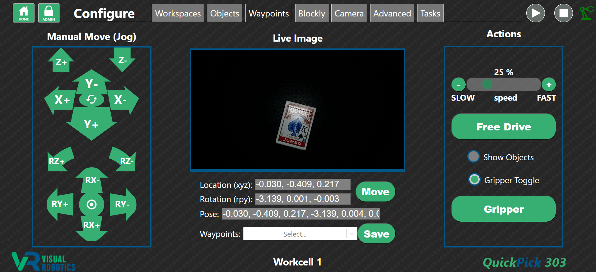
Figure 17: Waypoints Tab
Press the Free Drive button (which will become outlined in white) to cause the robot to be easily moved by hand to a new location. Press the Free Drive button again to disable this mode when you have arrived at the desired location. The Manual Move (Jog) buttons can be used to fine-tune the position.
The Gripper button can either be momentary or toggle, depending on the state of the Gripper Toggle button. The Gripper button is used to manually enable the end effector for testing.
The Jog Speed slider is used to set the speed of manual movement (jogging) as well as the speed of moving to waypoints.
The Manual Move buttons - Jog Panel (Figure 18) allow the programmer to move the robot in different directions and to aim the camera in different orientations. The Rotate Orientation button is not implemented in version 2.7.1 but is intended to allow the user to orient the jog buttons to match the direction that the operator is facing the robot. The bump at the bottom of the oval represents the orientation of the cable sticking out of the robot base. The bullseye shaped Aim Straight Down button* aims the camera directly downward, which can be convenient to create a waypoint in a particular orientation.
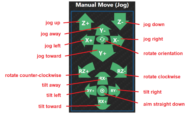
Figure 18: Jog Panel
The center panel on the Waypoints tab displays the live image. Depending on the state of the Show Objects button, the displayed image is either the raw image from the color camera or the annotated image from the image processing algorithm (the Finder), as shown in Figure 19. The coordinate readout shows the current 6DOF pose (in meters and rotation vector, per the Universal Robot convention). The (X,Y,Z) location and rotation (in roll, pitch, yaw format) is also shown. In addition to being a readout display, the values can be changed by the programmer by clicking into the boxes. The current location of the robot is shown in gray. If a waypoint is selected that is at a different location than the current location, the readout will show in yellow.
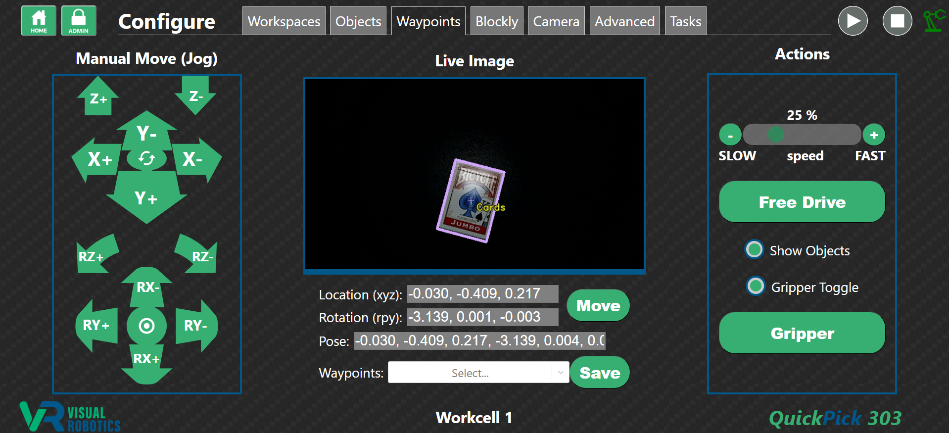
Figure 19: Live Image with Show Objects enabled
The programmer can select an existing waypoint from the pulldown menu (Figure 20). Its coordinates will show up, either in gray if this waypoint is at the robot’s current location, or in yellow if is different from the current location (Figure 21). When the programmer presses the Move button, the robot will move to that location. Then the display will turn gray to indicate the current location is being displayed (Figure 22).
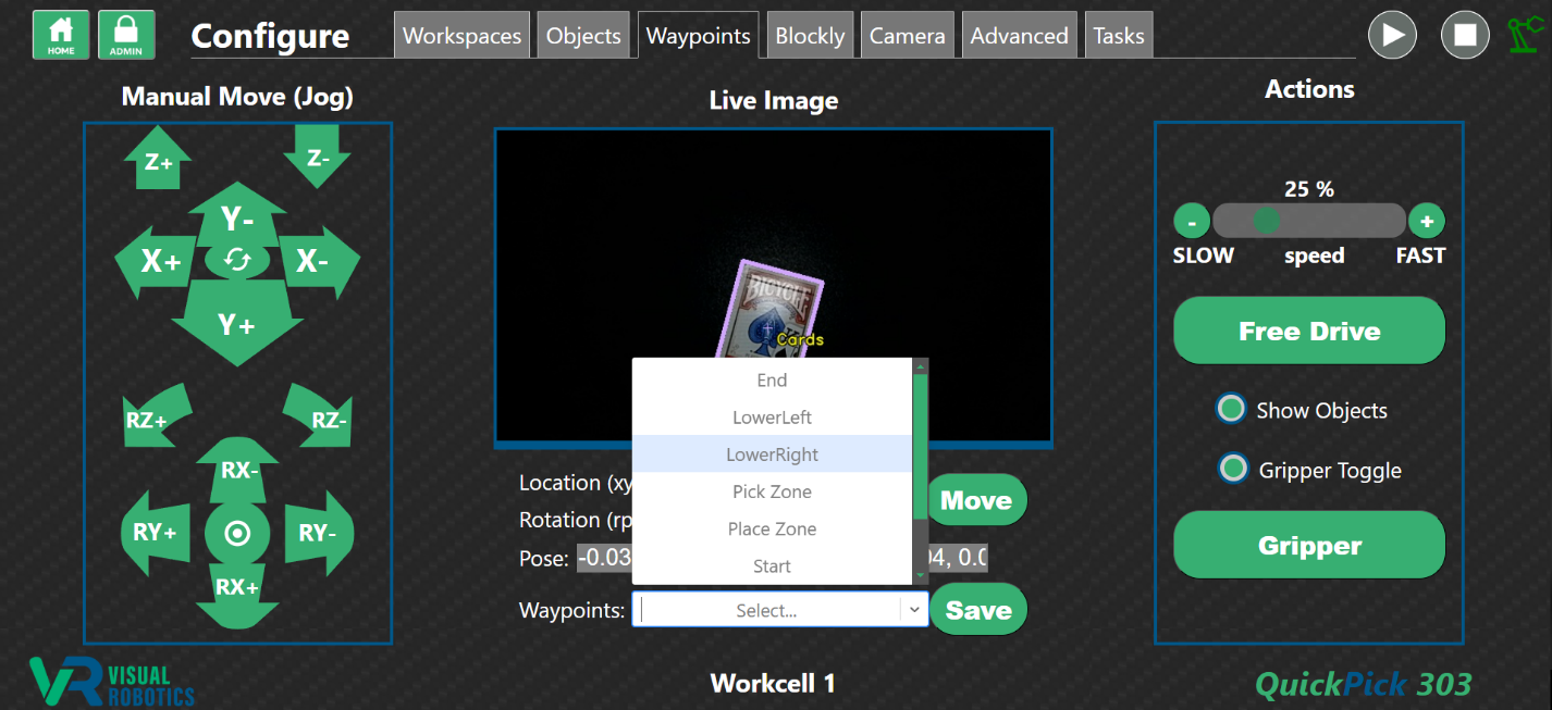
Figure 20: Selecting a Waypoint
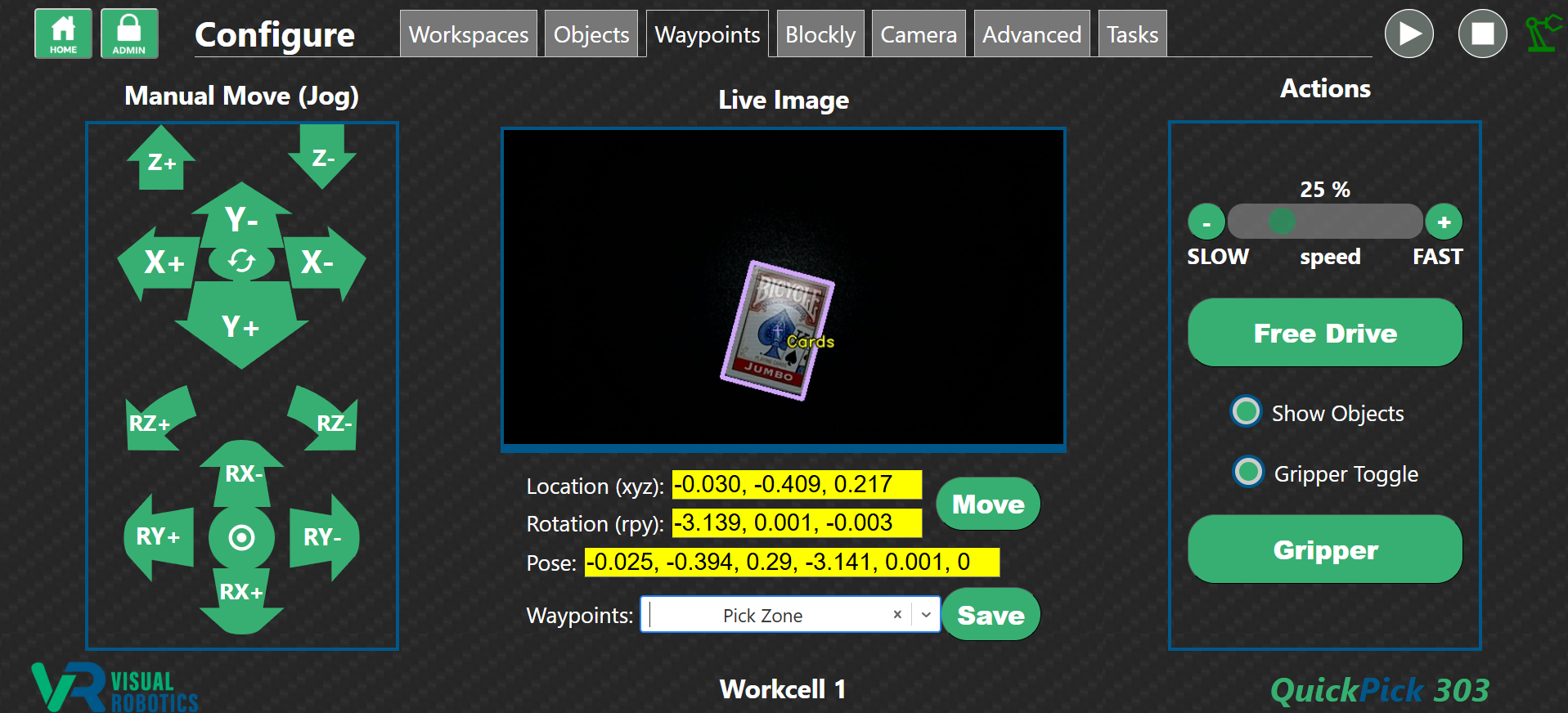
Figure 21: Waypoint different from the current location
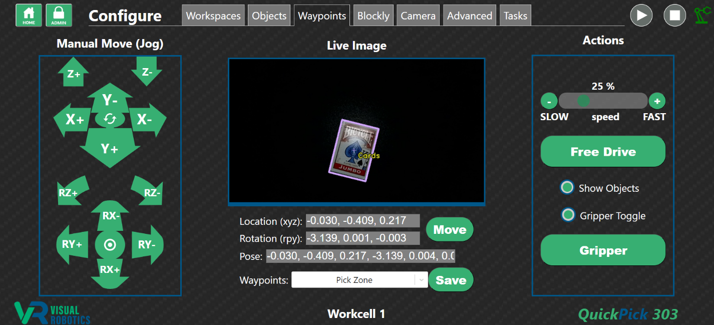
Figure 22: Move to Waypoint
New waypoints are created when the programmer types the name into the waypoint box. A popup saying Create “waypoint” will appear (Figure 23). The programmer presses the popup to save the current location as the new waypoint. To save the current location and override the previous location stored in a waypoint, the programmer would press the Save button. Waypoints are deleted by pressing the X button next to the waypoint.
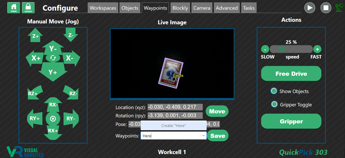
Figure 23: Create a new Waypoint
Visual Waypoints are waypoints that are defined based on the top-center location of an object within the field of view (Figure 23B). With a single object in the field of view (known or unknown), create a waypoint that begins with an asterisk (*). This signifies that the waypoint should be created at the top-center of the visible object, rather than at the current robot’s position. For example, in Figure 23B, the waypoint *Cards is created. The waypoint’s location becomes the top-center of the deck of cards visible to the camera. This is a powerful method for creating waypoints by viewing objects in the field of view. For example, to set the four waypoints needed to specify a pallet, a box could be selectively moved to the four corners and four visual waypoints created while the camera is viewing the scene.
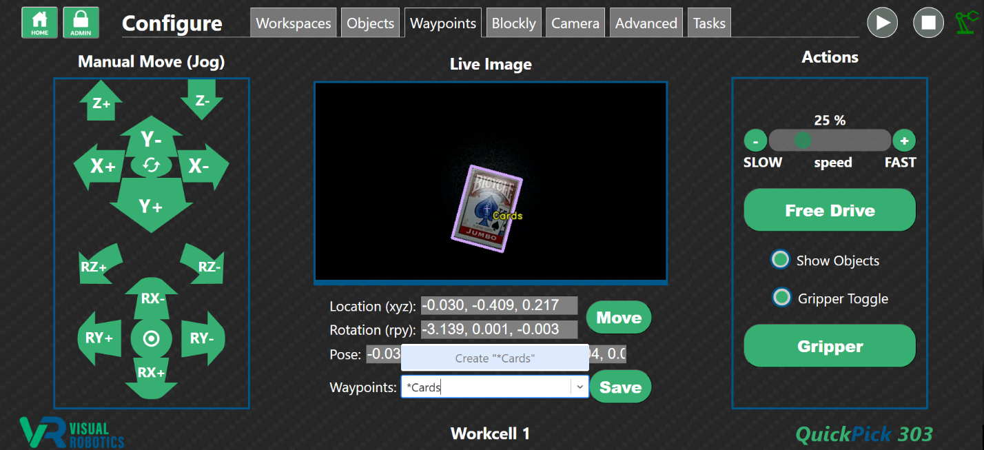
Figure 23B: Create a Visual Waypoint
Blockly Tab
The Blockly tab is where the programmer creates Blockly Tasks (programs) for the operator to run (Figure 24). Blockly is a graphical programming language developed by Google. The programmer clicks on the Toolbox panel to choose a programming block and places it on the programming Canvas to create the program (Figure 25). Every program starts with the start block, which is where the program starts execution when the Start button is pressed.
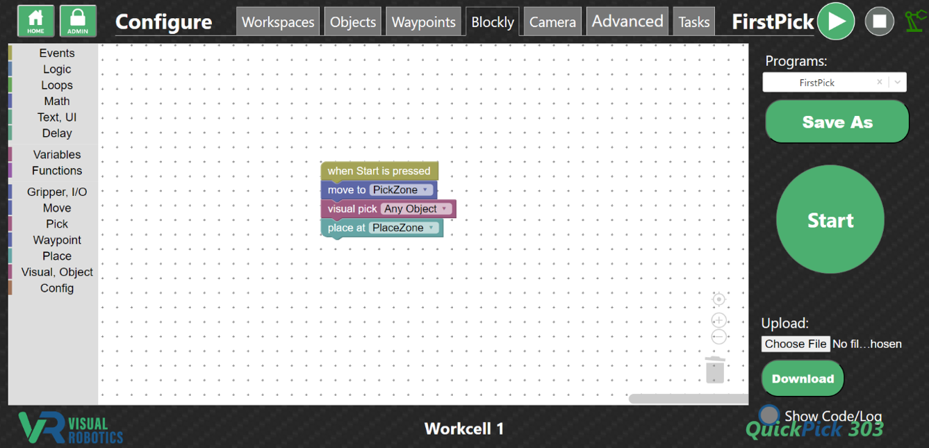
Figure 24: Blockly Editor
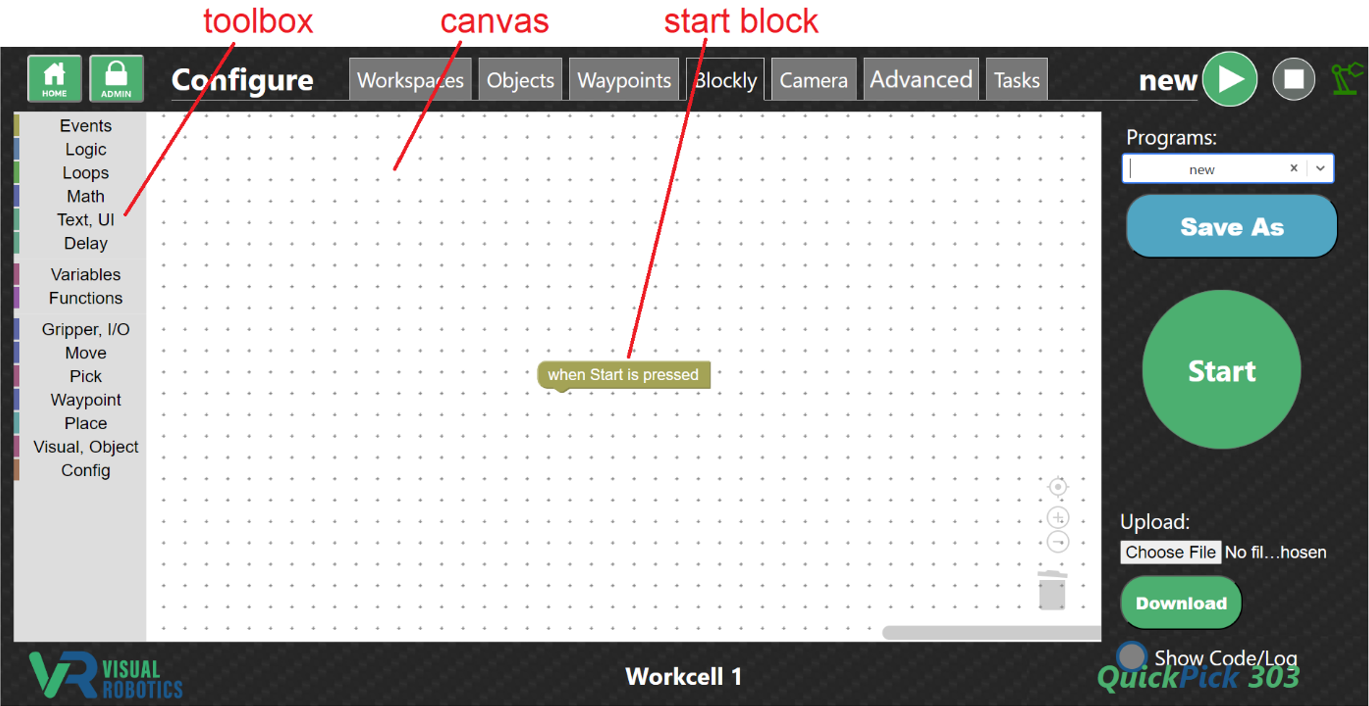
Figure 25: Blockly Editor Toolbox and Canvas
Select the Task (program to load) by selecting from the pull-down menu (Figure 26). The programmer can save the program by pressing the Save As button and choosing the filename (Figure 27). A new program is created when the programmer types the Task name in the program box.
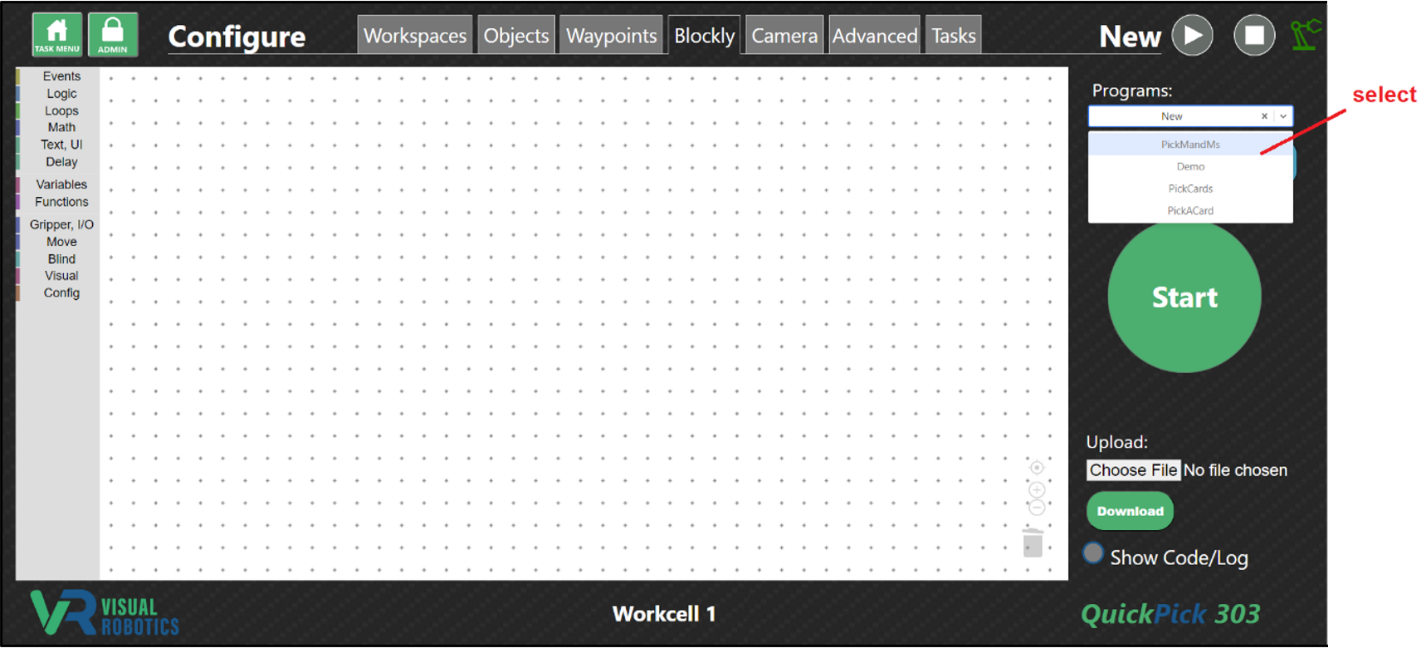
Figure 26: Select Program (Task)
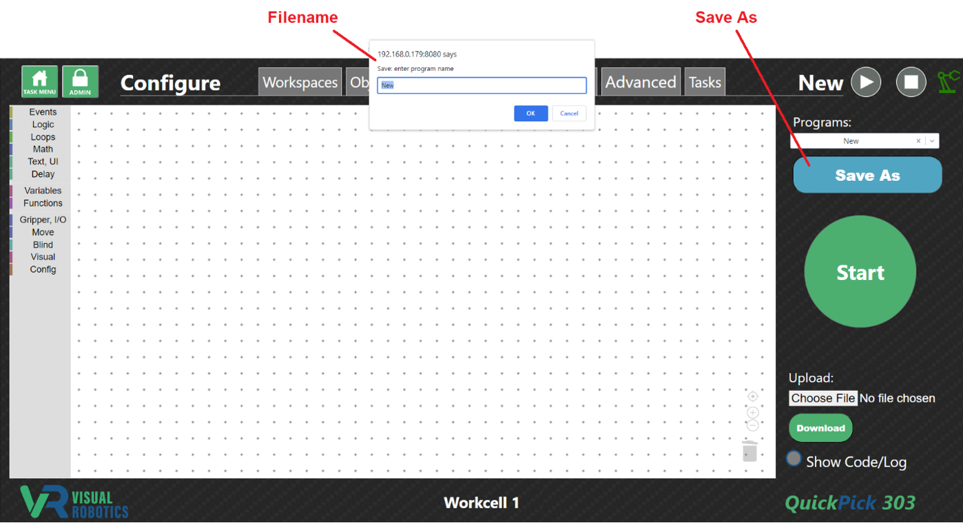
Figure 27: Save Program (Task)
Clicking on a category in the Toolbox shows the list of blocks in that category, for example, Loops (Figure 28). Clicking on a block in the category places it on the Canvas. Other blocks can be chosen and slid into place. They click when they attach to a compatible block (Figure 29). A full list of blocks and their behavior can be found in the Blockly Programming Manual.
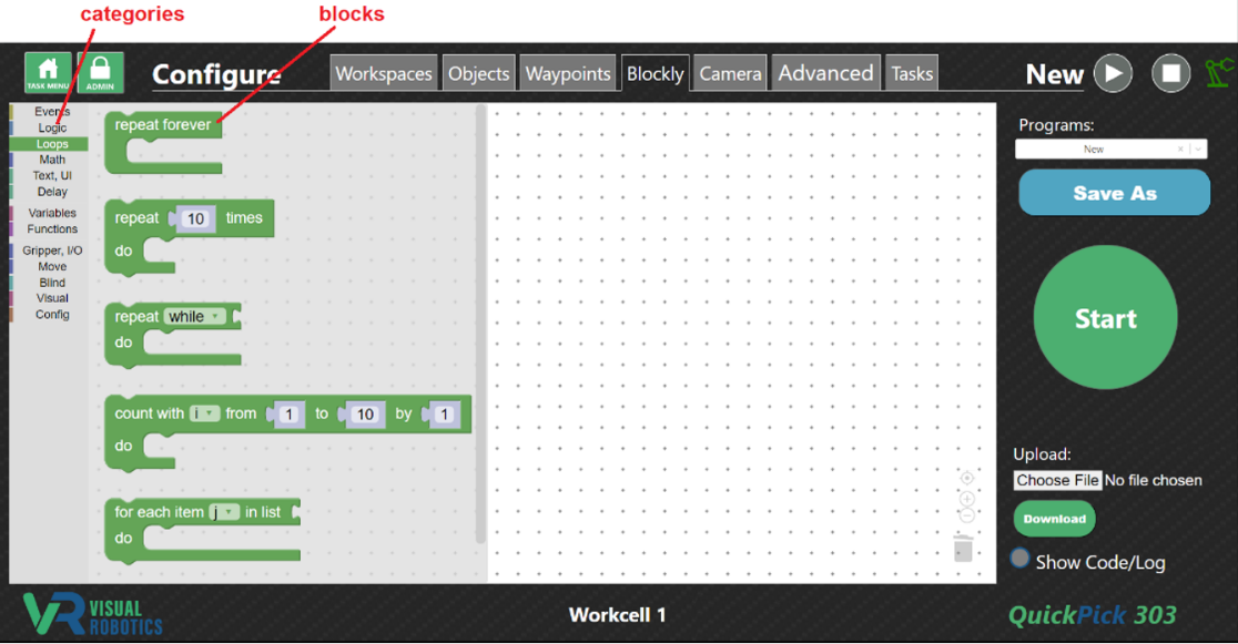
Figure 28: Selecting the Loops Category
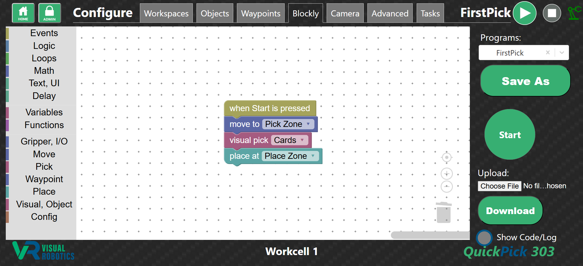
Figure 29: Creating a Program
Figure 30 shows step-by-step how to create a trivial program that repeatedly moves somewhere, to show how the Blockly editor is used. First, select the Start block from the Events menu (1). Select the Repeat block from the Loops menu (2). It defaults to repeating 10 times. Choose the Number block from the Math menu and change the value to loop 5 times (3). Add a Move block from the Move menu (4). It defaults to nowhere. Change the waypoint in the pulldown menu to PickZone (5).
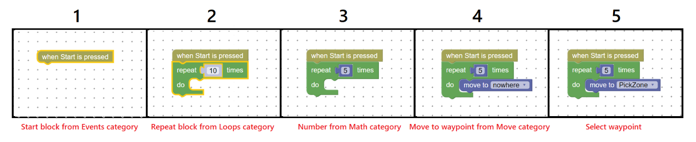
Figure 30: Creating a Program - step by step
Press the Start button to run the program. It will change to a Stop button which stops the program when pressed. If pressing Stop doesn’t stop the program, it is executing a command that takes a while to respond; press Stop again.
Press the Show Code/Log button to see the Python code that corresponds to the Blockly program and the log of print statements and code execution (Figure 31). The first 4 lines of the Python code connect to the camera using the XML-RPC interface. The remainder of the program consists of a translation of the Blockly commands to the equivalent Python commands.
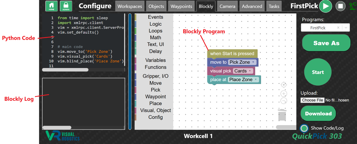
Figure 31: Show Code to see Blockly program translated to Python code
Camera Tab
The Camera tab (Figure 32) allows camera parameters, illumination settings, and debug image preferences to be adjusted. This provides a subset of the full parameter set available in the Advanced tab but shows a live image so that the change in the settings can be immediately seen. Choose a Module (either camera or debug image) from the pulldown menu. Choose one of the Settings from the pulldown menu. Change the value and press Set Value. Press Save to save the setting, so it is retained upon power cycling. The table on the right side describes the setting, its allowable values, default value, and current value.
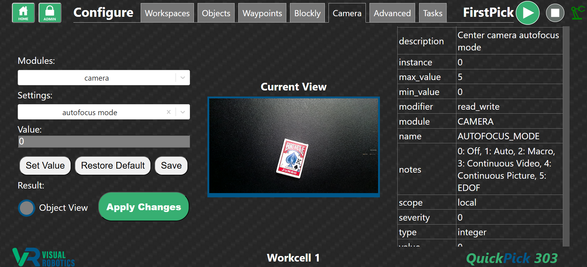
Figure 32: Camera Tab
Advanced (Settings) Tab
The Advanced tab allows the programmer to modify any of the settings for the VIM-303 vision guidance system (Figure 33). Settings are divided into categories called Modules. Selecting one or more Modules in the pulldown menu limits the displayed settings to those categories (Figure 34). An individual Setting within the module is chosen from the pulldown menu (Figure 35). The current value is displayed in the Value box. The table on the right side provides details about the setting, including its current and default value. The programmer can change the value by typing in the Value box. The value is not changed until the Set Value button is pressed. The Default value can be restored to the setting by pressing the Restore Default button. The settings are not saved after powering off the camera unless the programmer presses the Save button. Description of the operation of all of the Settings are described in the Settings Manual.
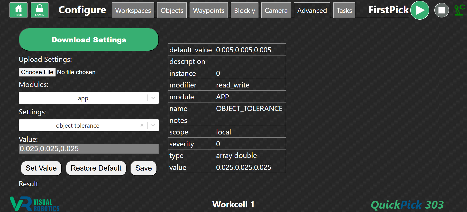
Figure 33: Advanced Tab
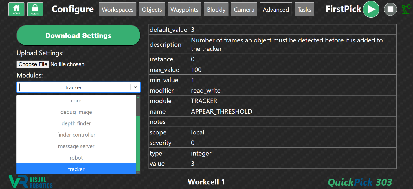
Figure 34: Select a Module
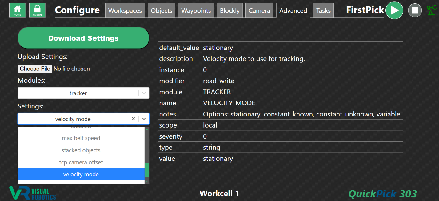
Figure 35: Selecting a setting within a module
Tasks Tab
The Tasks Tab allows the programmer to organize the layout of the Task Menu for the operator (Figure 36). Every program from every workspace shows up in the menu tree in the Task Menu Layout section of the Tasks Tab.
Folders can be created by pressing the New Folder button. Select an item (either a folder or task) by clicking on it, and it will be outlined in white (Figure 37). Drag an item onto a folder to place it inside the folder or drag it somewhere else in the menu tree. When an item is selected, the available actions (buttons) will be shown in green. Folders can be renamed and deleted. Tasks cannot be renamed or deleted from this tab but are changed in the Blockly tab.
The show/hide toggle allows the programmer to hide folders and tasks (Figure 37). Hidden tasks and folders are shown in gray (Figure 38). Hiding folders and tasks can be useful to allow the operator to only execute selected programs. It can also be useful for version control, to show only the latest version of a task.
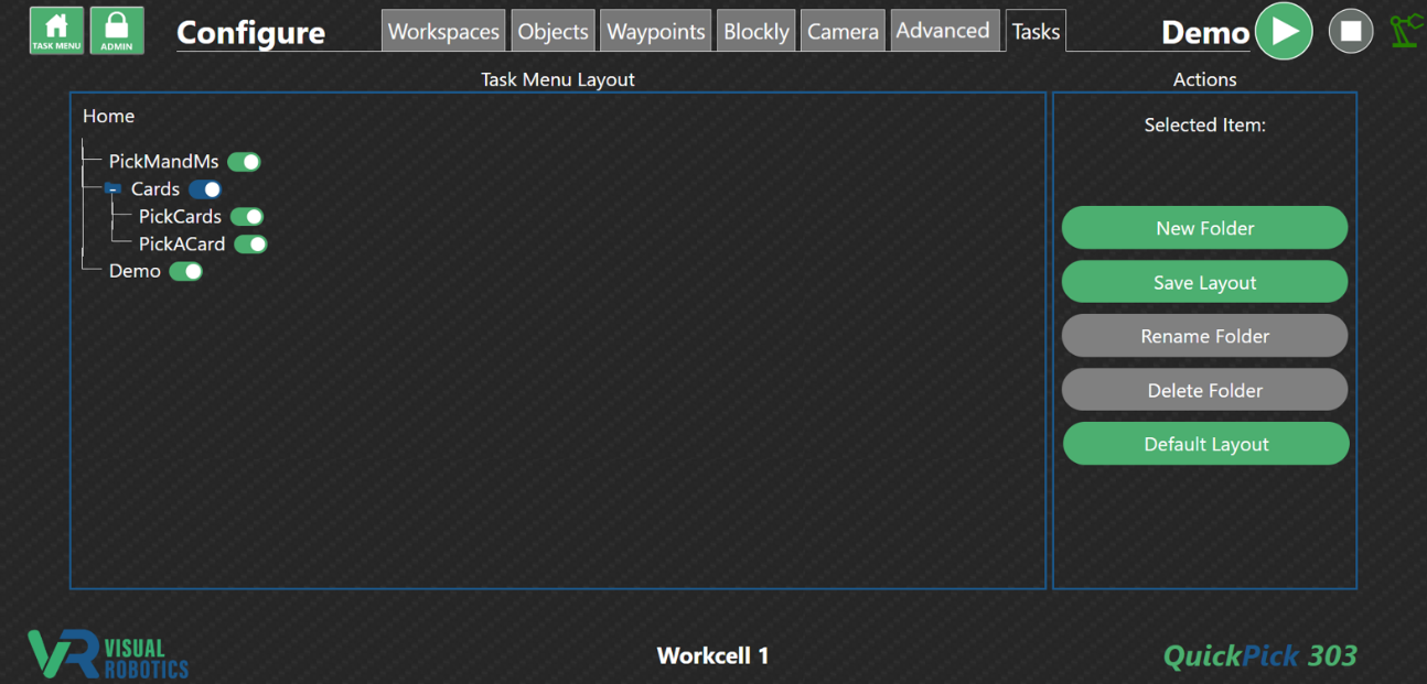
Figure 36: Tasks Tab
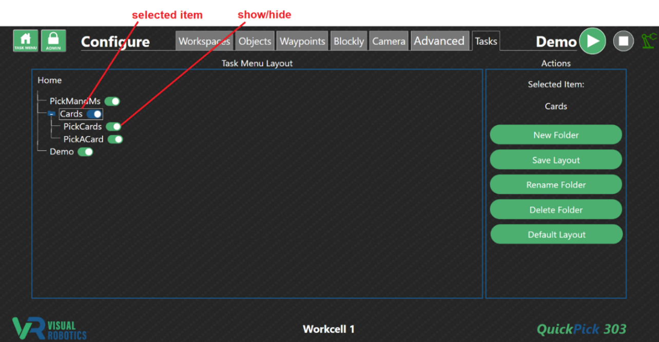
Figure 37: Selected Item
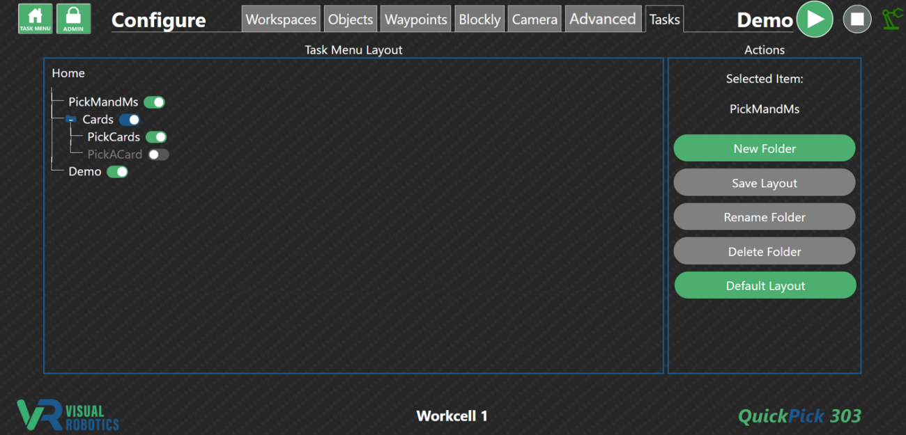
Figure 38: Hidden Task
Figure 39 shows a sample Task Menu Layout tree and the operator’s view of the Task Menu. PickMandMs is a task at the Home level of the Task Menu, and a Cards folder is the other item at the Home level. If the operator clicks into the Cards folder, two tasks are shown, PickCards and PickACard.
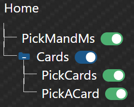
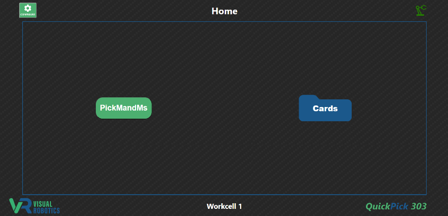
Figure 39: Task Menu Layout tree and operator’s view of Task Menu