Administration
The Administration panel allows an Administrator to view the status of the VIM-303 camera, set up the camera’s connection to a robot using PolyScope, update camera firmware and reboot the camera. The programmer arrives at the Administration panel by pressing the Admin button (Figure 40) from any tab in the Configure menu.
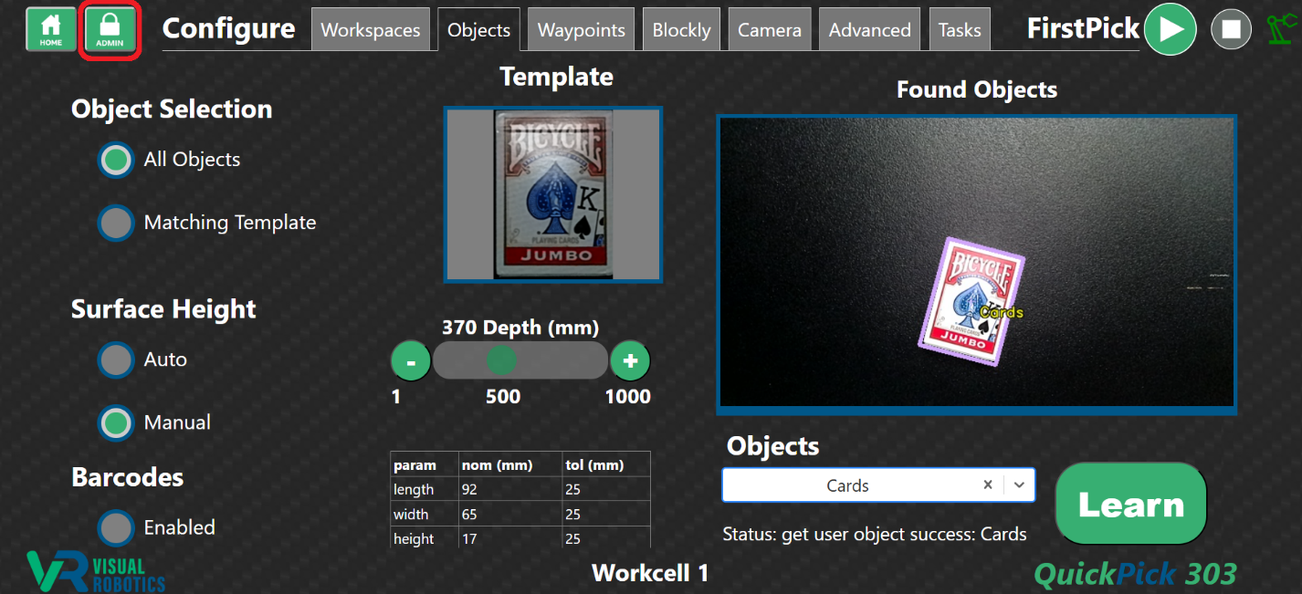
Figure 40: Going to the Administration panel
Log Tab
The Log tab shows various real-time logs of different parts of the system for troubleshooting purposes. The Application Log (Figure 41) provides debug information from the camera, finders, tracker, and robot controller components of the VIM-303 vision guidance system. The verbosity of the log level can be adjusted in the Settings tab in the Core module. The Web Server Log (Figure 42) shows the requests and responses to the on-board web server. The Blockly Log (Figure 43) shows the program state and output of Print blocks. It can also be viewed on the Blockly Tab by pressing the Show Code/Log button. The System Log (Figure 44) provides logging from the Linux operating system.
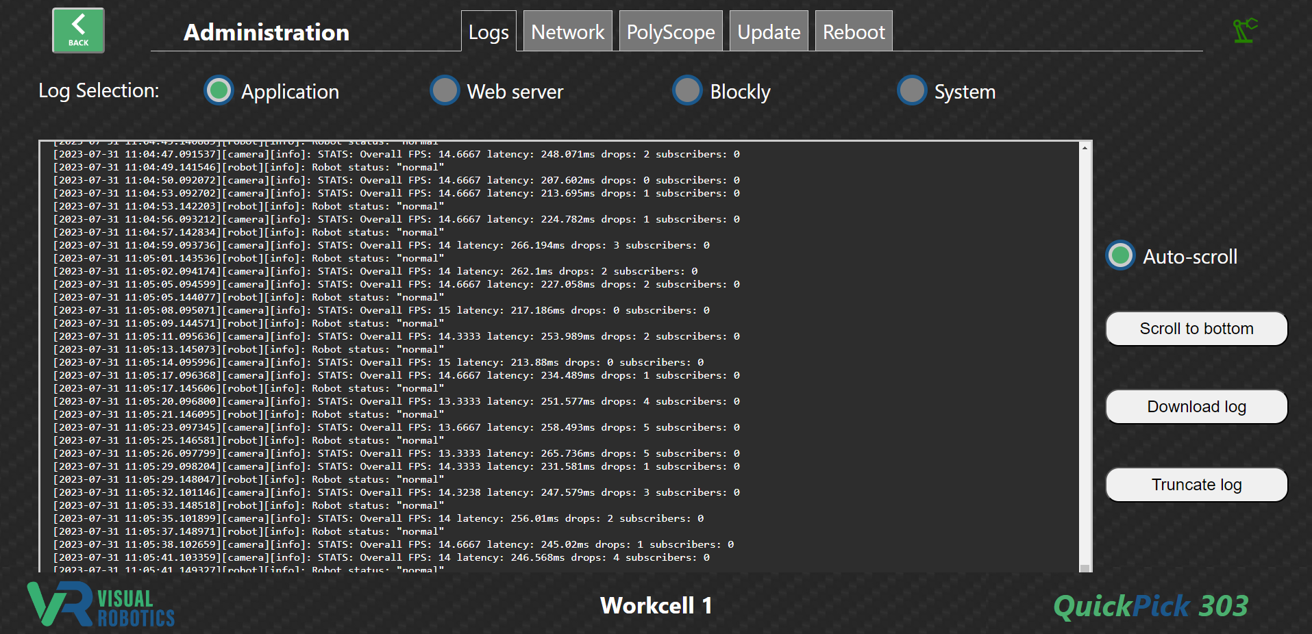
Figure 41: Application Log tab (showing Application log)
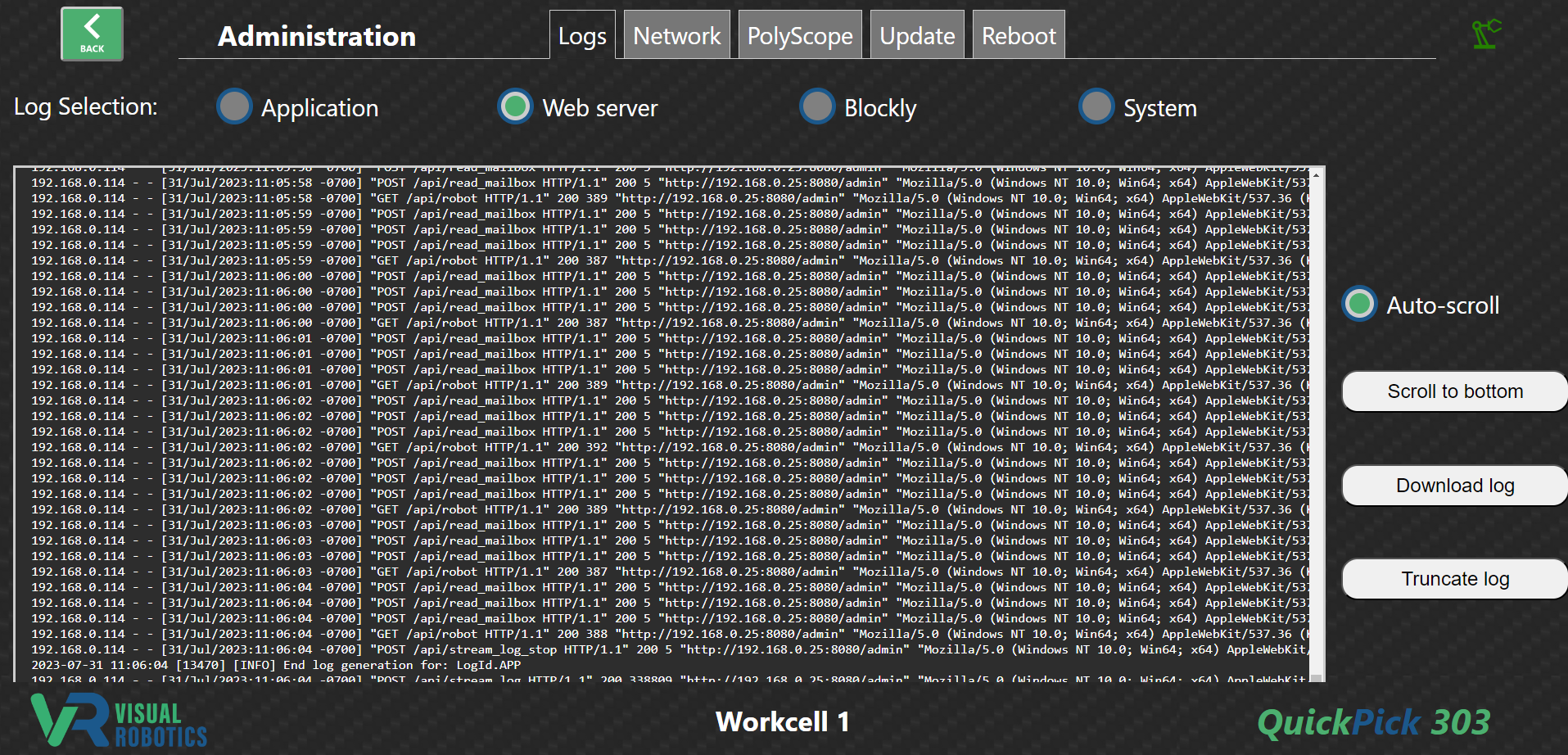
Figure 42: Web Server Log tab
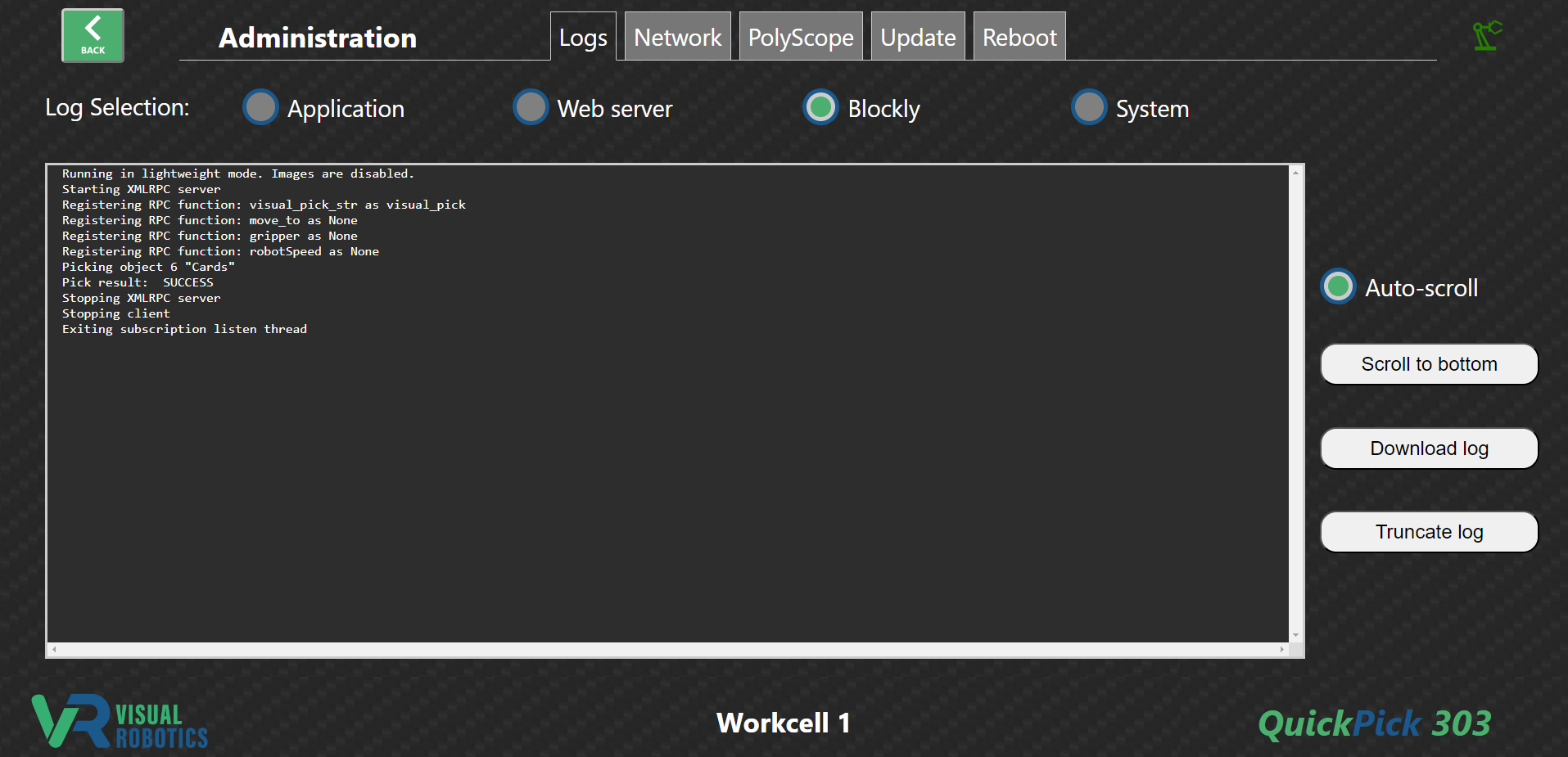
Figure 43: Blockly Log tab
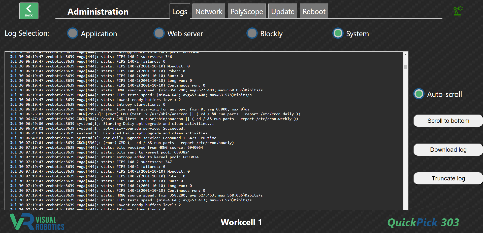
Figure 44: System Log tab
Network Tab
The Network Tab (Figure 45) shows the IP addresses and network name of the VIM-303 camera. Figure 46 shows what network addresses the camera will use, depending on the existence of a DHCP server and the value of the IP Address Setting (in the Robot module in the Settings tab). Under some circumstances, there will only be a single IP address, so only a Primary IPv4 address will be shown on the Network tab. In other circumstances, the camera will have two IP addresses, the static address and the DHCP address. The mDNS Host Name matches what is printed on the back of the camera. The camera can be located using mDNS using the suffix .local as in vrobotics8639.local in the example of Figure 45.
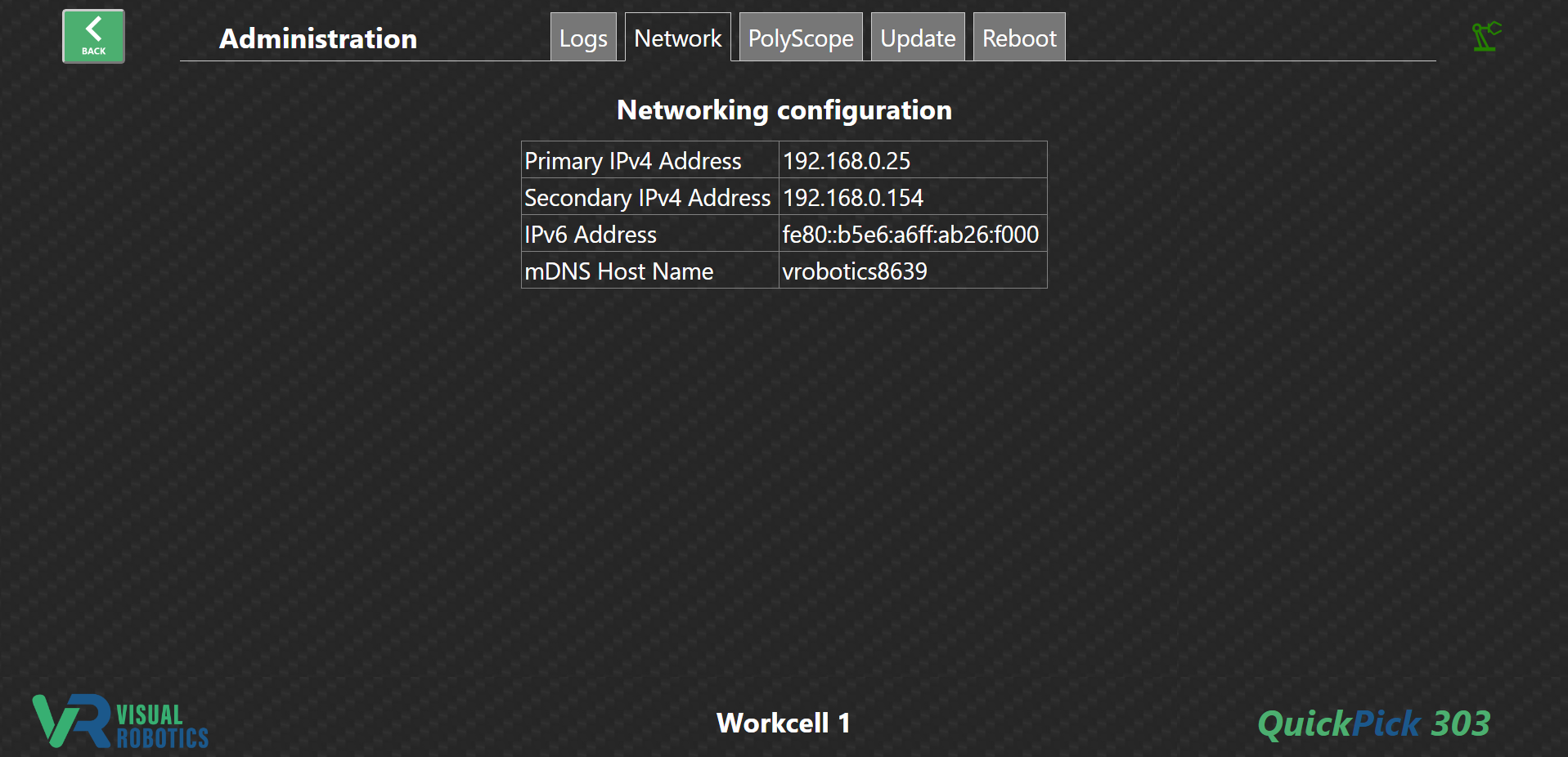
Figure 45: Network tab

Figure 46: Camera IP Address Options
Polyscope Tab
The PolyScope Tab has a single button Save Command Processor (Figure 47). When pressed, this button copies the VIM-303 command processor to the Universal Robot at the IP address specified in Robot IP in the Robot module of the settings tab. The command processor controls the robot to implement visual picking and placement. In addition to the command processor, a sample PolyScope program is copied to the robot that shows how the VIM-303 can be commanded from PolyScope to implement visual picking.
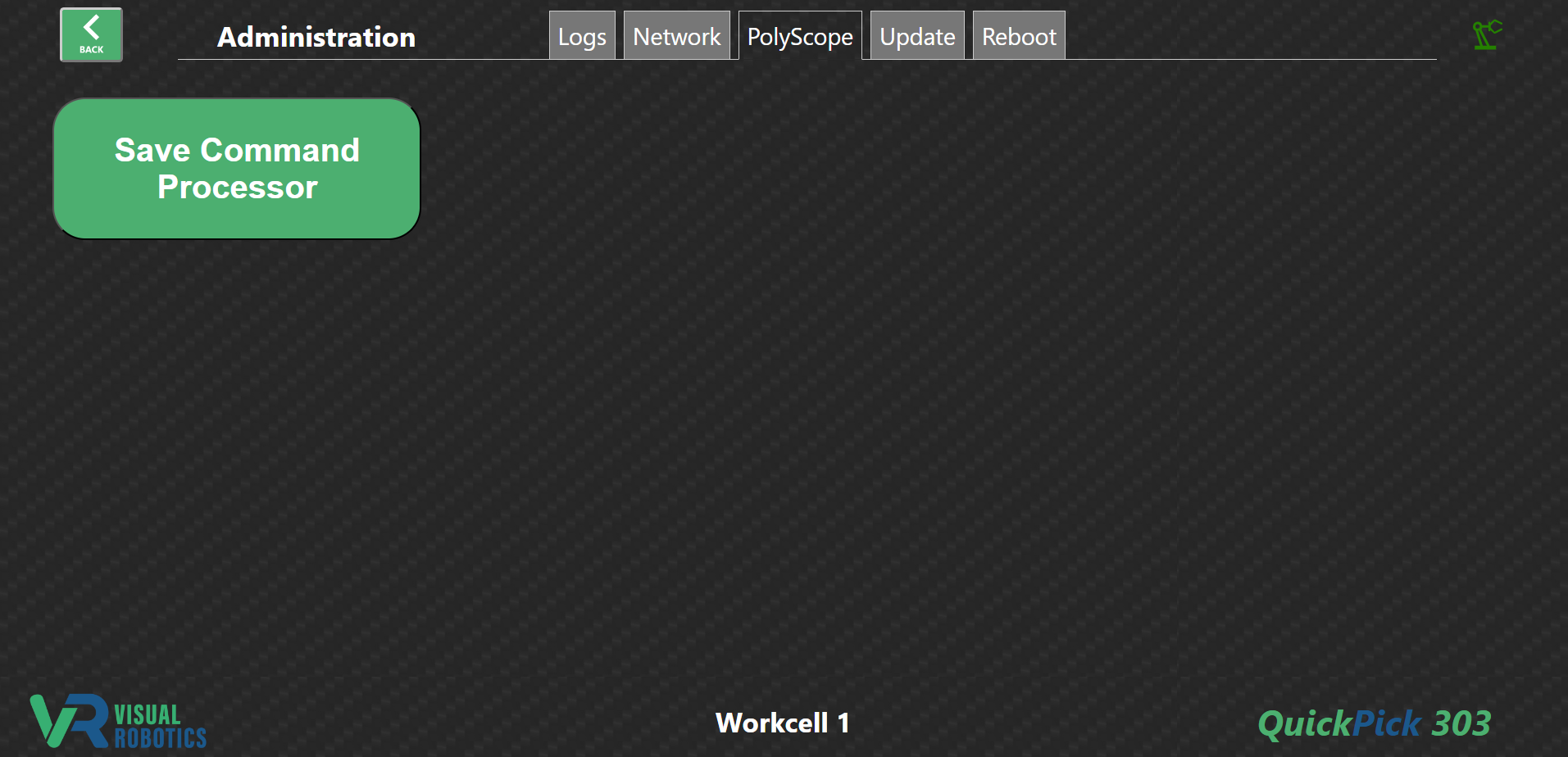
Figure 47: PolyScope Tab
Update Tab
The Update Tab is used to update firmware on the VIM-303 camera (Figure 48). The current firmware version is listed at the top of the screen. Press the Choose Files button to select a file from your PC to send to the camera (Figure 49). The Update Camera button will turn green (Figure 50). Press it to begin the firmware update. The camera will restart (you may need to refresh the page), and the Current Firmware will indicate the recently updated firmware version.
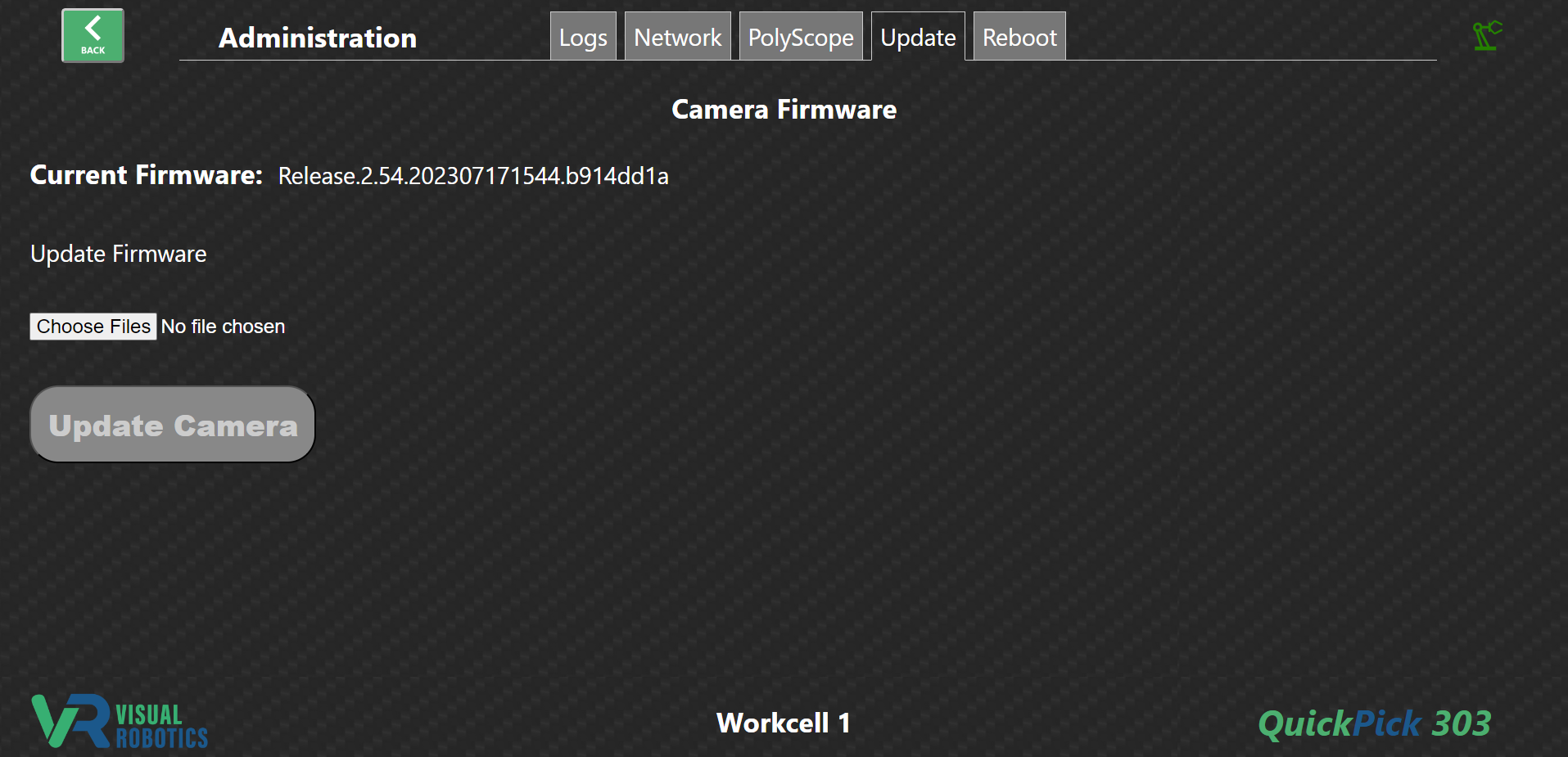
Figure 48: Update firmware tab
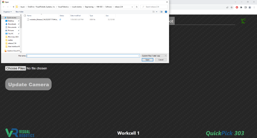
Figure 49: Select firmware file from PC
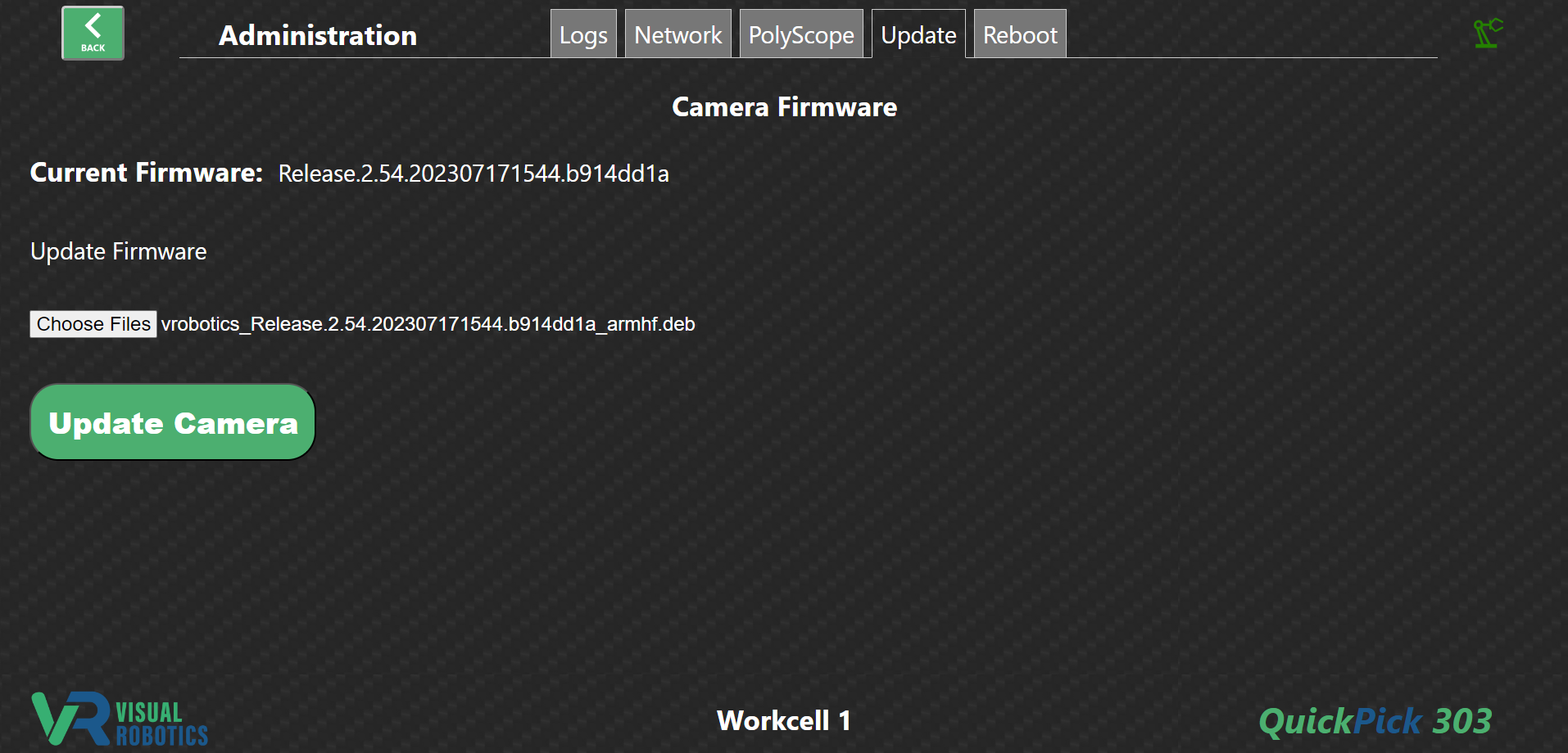
Figure 50: Update Camera button to upgrade firmware
Reboot Tab
The Reboot Tab is used to reboot the camera (Figure 51). If the camera is unresponsive or under the direction of a Visual Robotics technician, rebooting the camera may be required to restore proper performance. Press the Reboot Camera button and after a while (perhaps a minute) the camera will be restarted. You may need to refresh the webpage.
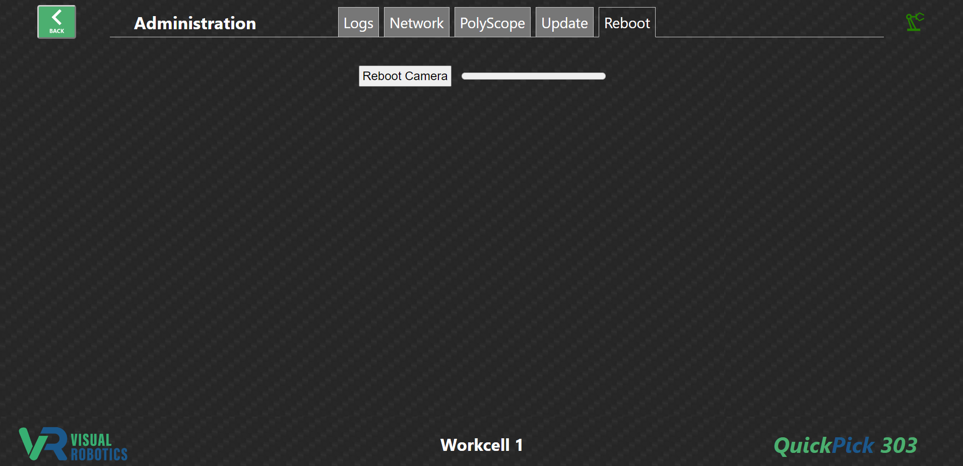
Figure 51: Reboot tab