Blockly Code Generator
On the VIM-303 camera, Blockly is used as a Python code generator. The Blockly program’s blocks are compiled into Python code which is executed by the VIM-303 camera to perform the Programmer’s intended behavior. Each block of Blockly code typically compiles into a single Python statement that typically makes calls to the camera’s VIM API (Vision-in-Motion Application Programming Interface).
Toolbox
The Toolbox categorizes every Blockly block that the Programmer can use to program the VIM-303 camera (Figure 1). Clicking on a category in the Toolbox shows the blocks in that category.
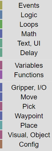
Figure 1: Blockly Toolbox
Events
The Events category consists of blocks that relate to starting and stopping the program (Figure 2). Figure 3 shows a table of the various event blocks and their function. Some blocks (such as “when Start is pressed”) can only be used once in the program. Since every program already includes this block on the blank canvas, it is shown dimmed.
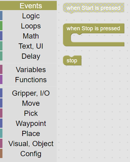
Figure 2: Events category

Figure 3: Events blocks
Logic
The Logic category (Figure 4) consists of an If statement and the associated comparison blocks. The If statement has a mutator (blue gear) that allows the If statement to morph into various forms, including else if and else clauses (Figure 5).
Click the gear to show the mutator menu. Move the desired block piece from the left to the right side of the pop up. Then press the gear to remove the pop up. Figure 6 shows a table of the various logic blocks and their function.
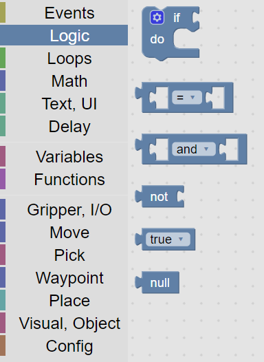
Figure 4: Logic category
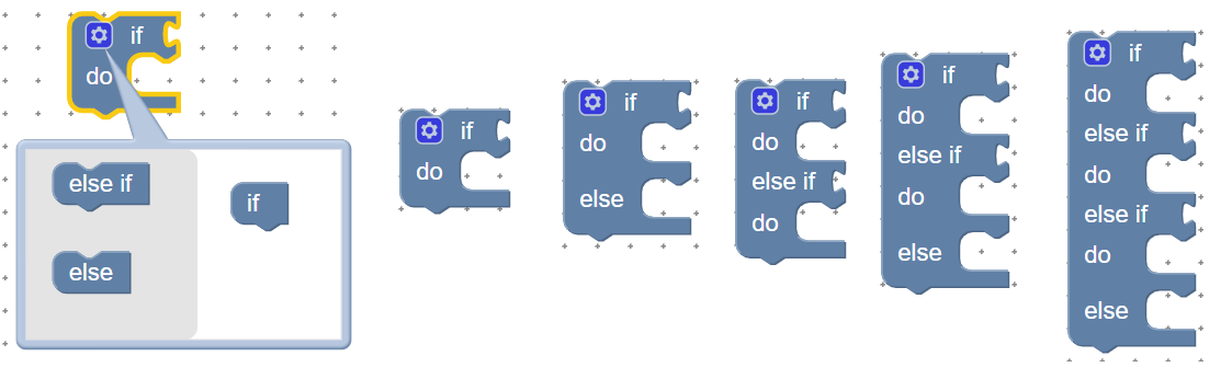
Figure 5: If statement mutator variants
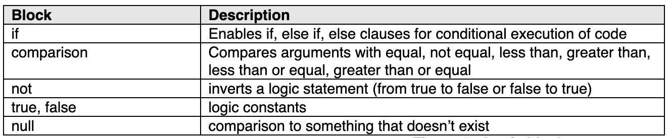
Figure 6: Logic blocks
Loops
The Loops category (Figure 7) consists of various ways to repeat code execution. Figure 8 describes the functionality of the various loop blocks.
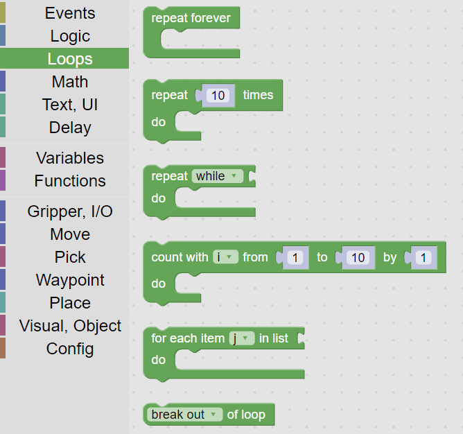
Figure 7: Loops categoryy
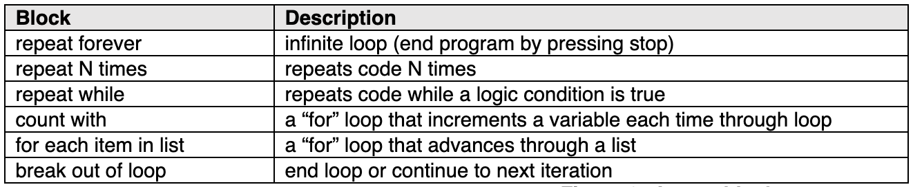
Figure 8: Loops blocks
Math
The Math category (Figure 9) provides numbers and arithmetic. Figure 10 describes the functionality of the math blocks.
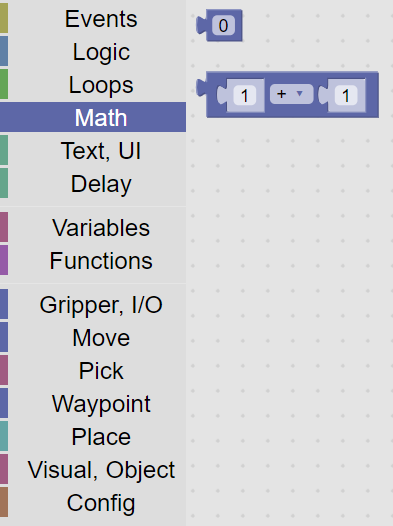
Figure 9: Math category

Figure 10: Math blocks
Text, UI
The Text, UI category (Figure 11) provides debug and code documentation blocks. Figure 12 provides a description of each of the blocks. The UI blocks are primitive [BH2] (displaying pop-up windows) but provide a method for modifying or regulating program operation by the user.
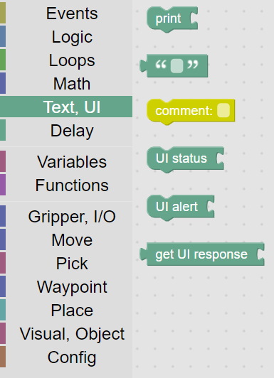
Figure 11: Text, UI category
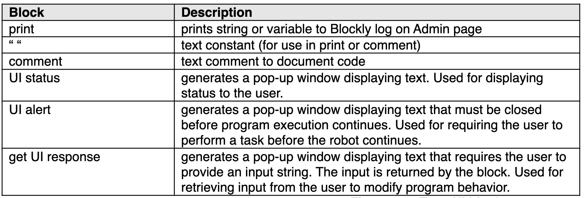
Figure 12: Text, UI blocks
Delay
The Delay category (Figure 13) provides a single function - a time delay, which is described in detail in Figure 14.
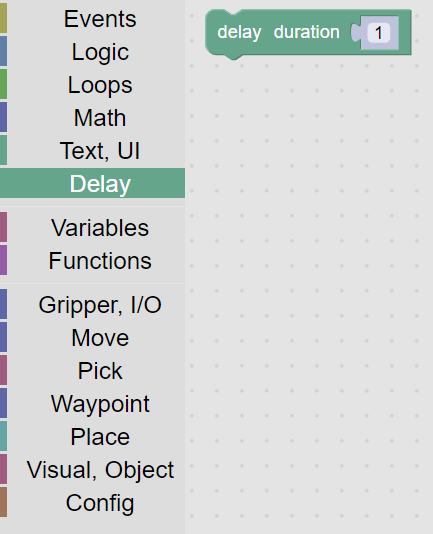
Figure 13: Delay category

Figure 14: Delay blocks
Variables
The Variables category (Figure 15) provides numeric, array, boolean, or string variables that can be set and read.[BH3] Figure 16 describes the blocks in detail.
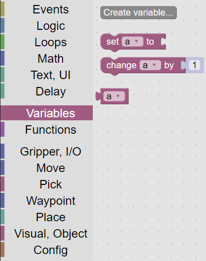
Figure 15: Variables category

Figure 16: Variables blocks
Functions
The Functions category allows the programmer to create subroutines and execute them (Figure 17). The Function block has a mutator to allow variables to be passed. When a new function is created, new blocks are created that allow you to call the function (Figure 18).
For example, for the function “do something” the code for the function is in the block “to do something” while calling the function is “do something”. Figure 19 lists each of the blocks in the function category.
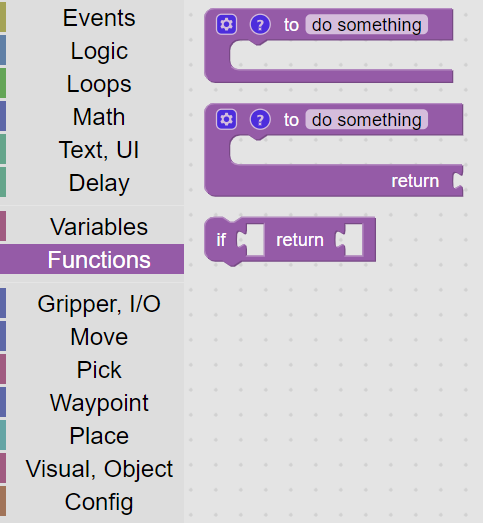
Figure 17: Function category
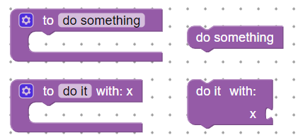
Figure 18: Defining and calling functions

Figure 19: Function blocks
Gripper, I/O
The Gripper, I/O category combines I/O functions supported by the robot controller, including actuation of grippers, digital input, and digital output (Figure 20). Macro blocks which wait for an input to change and to set an output for a certain period of time simplify code development and readability. The list of Gripper blocks is shown in Figure 21.
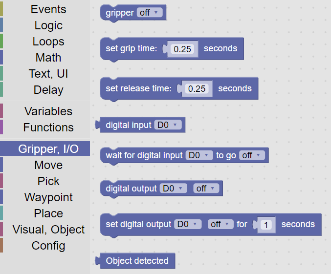
Figure 20: Gripper category
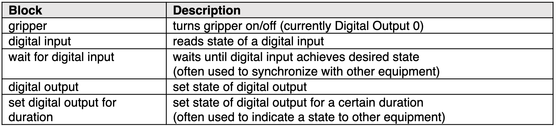
Figure 21: Gripper blocks
Move
The Move category provides blind moves, adjusts robot speed, and provides a list of waypoints created from the Waypoints Editor (Figure 22). Moves by default move to “nowhere”, which does nothing. When a move block is placed in the canvas, the desired waypoint is selected from the pulldown menu. The list of all of the move blocks is described in Figure 23.
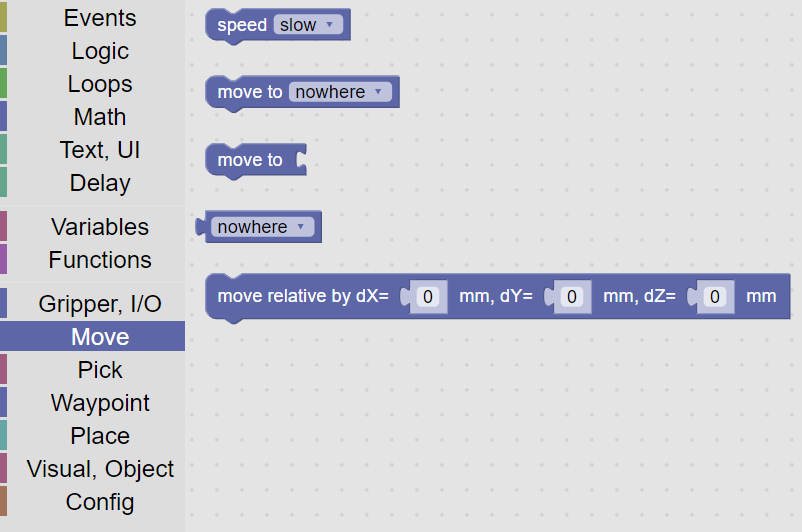
Figure 22: Move category

Figure 23: Move blocks
Pick
The Pick category provides visual and “blind” picks (Figure 24). Visual Pick waits until the desired object is within the field of view, then moves to the object and picks it. The “blind” pick Pick At moves to the waypoint and picks whatever is assumed to be there. The Status Of Last Visual Pick block can be used to determine if the pick was successful. The Pick At With Offset can be used when the waypoint specifies a surface and the offset specifies the height of the object to be picked. For visual picks, the object defaults to Any Object (any object that is seen, whether trained or not), but can also be set to Known Object (any object that has been learned), Unknown Object (any object that has not been learned), or any specific object that has been learned. Waypoints (used for the blind pick blocks) default to nowhere but should be set to a valid waypoint. The list of all of the Pick blocks is described in Figure 25.
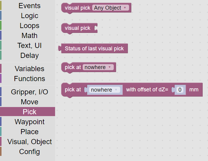
Figure 24: Pick category
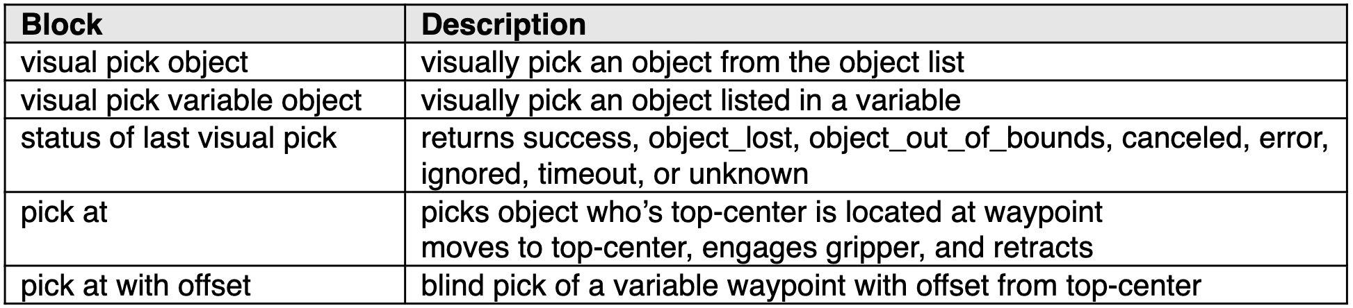
Figure 25: Pick blocks
Waypoint
The Waypoint category provides waypoints created on the Waypoints Tab (Figure 26). A variable can be set to a waypoint block, or the waypoint block can be used directly in various move, pick, and place blocks. The waypoints can be used directly as parameters for various move, pick, and place blocks. There is only one block in the Waypoint category, described in Figure 27. This block is also in the Move category for convenience.
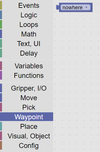
Figure 26: Waypoint category

Figure 27: Waypoint blocks
Place
The Place category provides blocks for placement (Figure 28). Some of the blocks specify a waypoint and are thus “blind” – moving to a predefined location. Other blocks take parameters for waypoints, which can be from a waypoint block (for blind placement) or from a variable (which could be set to a visual waypoint).
Place On assumes the top of the object is to be placed at the specified waypoint. The Place At With Offset block allows the surface to be defined by the waypoint, and the offset is typically the height of the object to be placed, which may be computed automatically as a result of a visual pick. This is used for visual placement or stacking. The Stack block is for blind stacking objects of known height. The Palletize block provides a high degree of flexibility in placing objects in a grid pattern, described in Figure 30. The list of the Place blocks is shown in Figure 29.
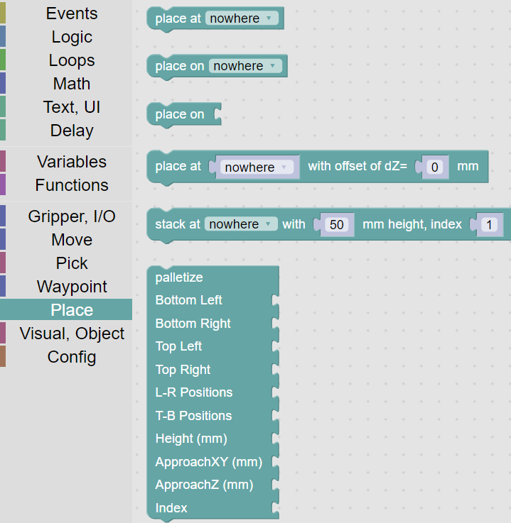
Figure 28: Place category
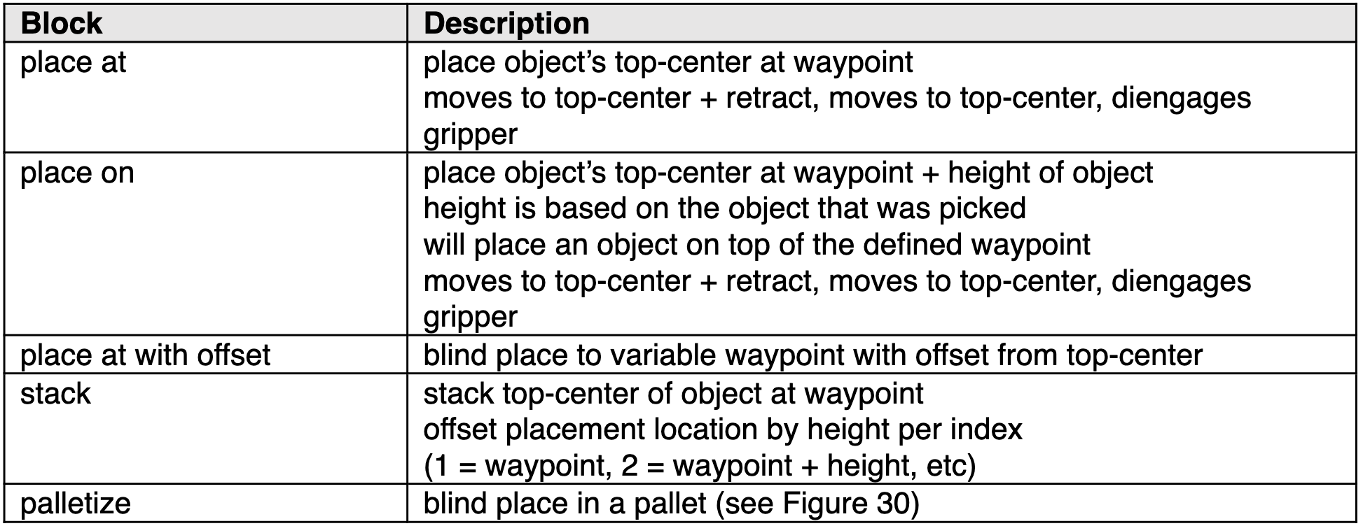
Figure 29: Blind blocks
Palletize
The Palletize block provides a high degree of placement flexibility. Figure 30 shows the five different configurations for this block, while Figure 31 shows the use of the block on the canvas for the various configurations.
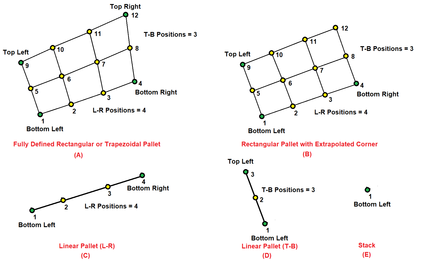
Figure 30: Pallet Configurations
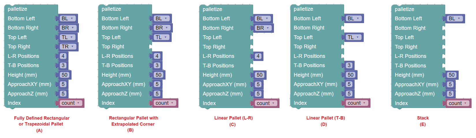
Figure 31: Pallet block usage
For each configuration, waypoints are used to specify the corner locations of the pallet by indicating the top-center locations of the object to be palletized. Up to four waypoints can be specified, to fully define the pallet geometry (A), which can have a rectangular, parallelogram, or trapezoidal shape. These waypoints are the Bottom Left, Bottom Right, Top Left, and Top Right. The blockly examples (Figure 31) show waypoint definitions (from the Waypoint or Move category) attached to the waypoint sections of the palletize block. Fewer than four waypoints can be specified, in order to create simpler palletization scenarios. For example, if the Top Right waypoint is unspecified, this location is extrapolated from the three specified points (Bottom Left, Bottom Right, and Top Left) as shown in example (B). Linear pallets can be specified using just two waypoints, using the Bottom Left and Bottom Right, shown in example (C), or using the Bottom Left and Top Left, shown in example (D). If only the Bottom Left waypoint is specified, the palletize block will simply stack at the Bottom Left waypoint, shown in example (E).
The number of grid positions between and including the Bottom Left and Bottom Right is specified by the L-R Positions parameter. Similarly, the number of grid positions between and including the Bottom Left and Top Left is specified by the T-B Positions parameter.
The Height parameter works the same way as it does for the Blind Stack block, which specifies the height between layers of the pallet, which is typically the height of the object being palletized.
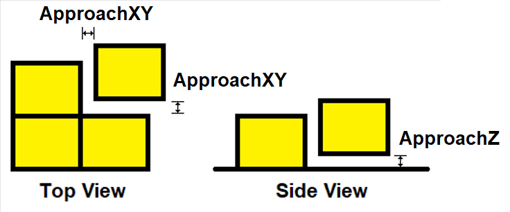
Figure 32: Clearance and Lift definition
The ApproachXY and ApproachZ parameters are illustrated in Figure 32. When performing blind palletization, it is helpful for the robot to bring the object close to its destination and then snug it up to other objects when close. The ApproachXY parameter specifies the lateral (X,Y) offset (in mm) for initial placement of the object before moving to the final position. The ApproachZ parameter specifies the vertical (Z) offset (in mm) from the final position when performing the initial placement. When palletizing an object with nonzero ApproachXY and ApproachZ parameters specified, the robot will move the object to the retract distance above the placement location, considering the clearance. It will then lower the object to the ApproachZ distance above the final placement location, offset in X and Y by the ApproachXY distance. It will then move to the correct (X, Y) lateral position, still offset in height (Z) by the ApproachZ distance, and then will finally lower the object to the final location. This is useful to achieve a close packing of boxes, for example.
The last parameter, Index, is a variable that starts at 1 to indicate the object should be set at the Bottom Left location. Incrementing Index will cause the palletize block to compute positions first along the L-R direction between the Bottom Left and Bottom Right and then increment along the T-B direction between the Bottom Left and Top Left and then increment in Height. The numbers in Figure 30 indicate the palletizing order for the first layer.
The names bottom, top, left, and right, are arbitrary. They specify the order that the palletizing algorithm will compute placement locations. Waypoints can be defined for a different purpose, but it may be useful for the Programmer to orient themselves when specifying waypoints so that the Bottom Left of the pallet is oriented accordingly.
Visual, Object
The Visual, Object category includes blocks to visually pick, observe, and identify objects (Figure 33). A list of all of the visual blocks is shown in Figure 34.
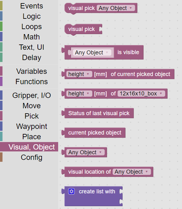
Figure 33: Visual, Object category
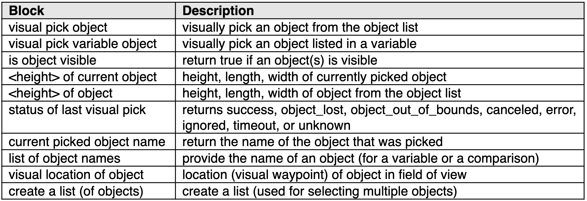
Figure 34: Visual blocks
One of VIM-303’s outstanding features is the ability to visually pick an object by name. The visual pick block allows the Programmer to specify the object to be picked from a pulldown list (Figure 35). The visual pick variable block allows the programmer to pick an object that is specified by a variable loaded with a string representing the object, enabling complex run-time behavior (Figure 35).
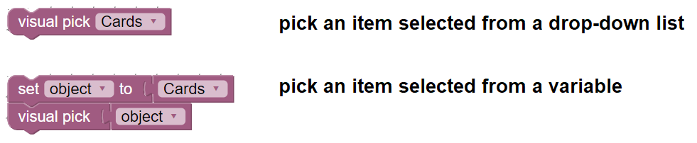
Figure 35: Visual pick examples
The create list block allows multiple objects (either variables or the list block) to be connected to the visual pick variable block. Figure 36 shows how multiple different objects can be picked, and custom behavior performed depending on which object was picked. For the visual pick one could select known object instead of a list to pick several types of objects and then perform custom tasks depending on which object was picked.
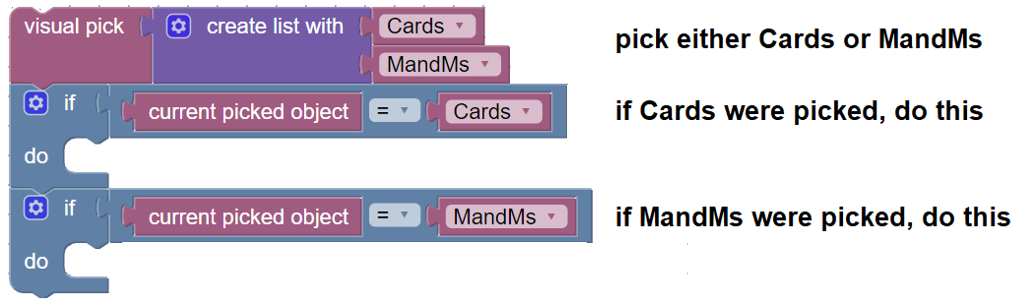
Figure 36: Visual pick of multiple items
Figure 37 shows how the status of the visual pick can be used to handle error conditions. Measurements of the current picked object such as the height is useful for providing offsets to the placement blocks. If an object is visually picked, the height of the object becomes known and can be used with the place on block to automatically place a picked object on top of a waypoint. The visual location of object block is very powerful for visual stacking as a visual waypoint variable can be created based on the visually observed top of a stack of objects. This can also be used for other visual placement tasks. An example of visual stacking is shown in Figure 38.

Figure 37: Error checking of visual picking
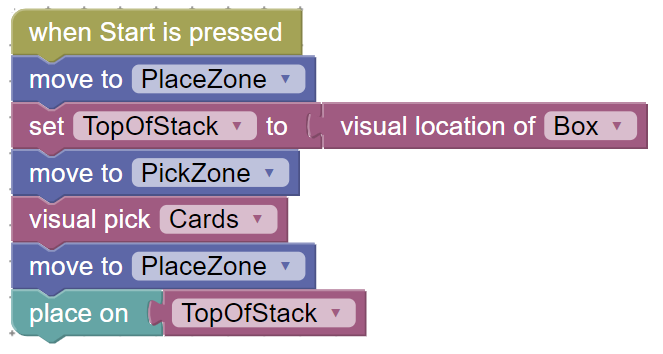
Figure 38: Visual stacking of objects
Config
The Config category provides the ability to change various system settings (Figure 39). Figure 40 tabulates the various types of configuration items that can be set in a Blockly program. Settings can also be set in the Advanced tab.
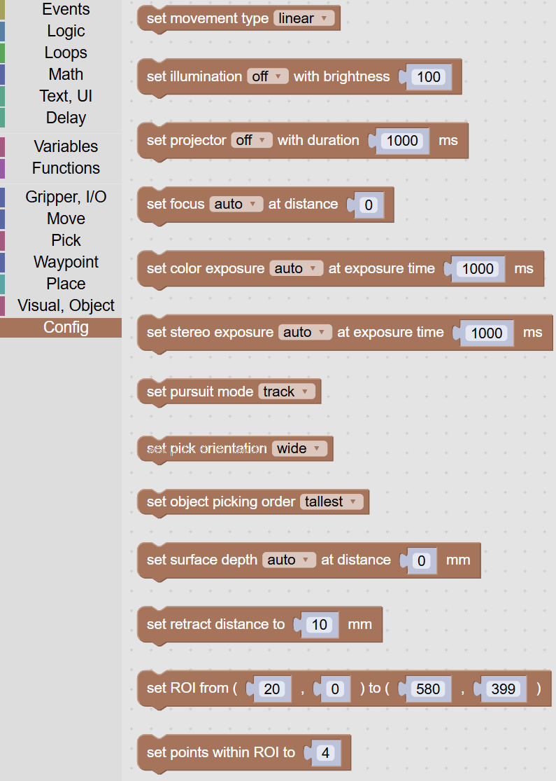
Figure 39: Config category
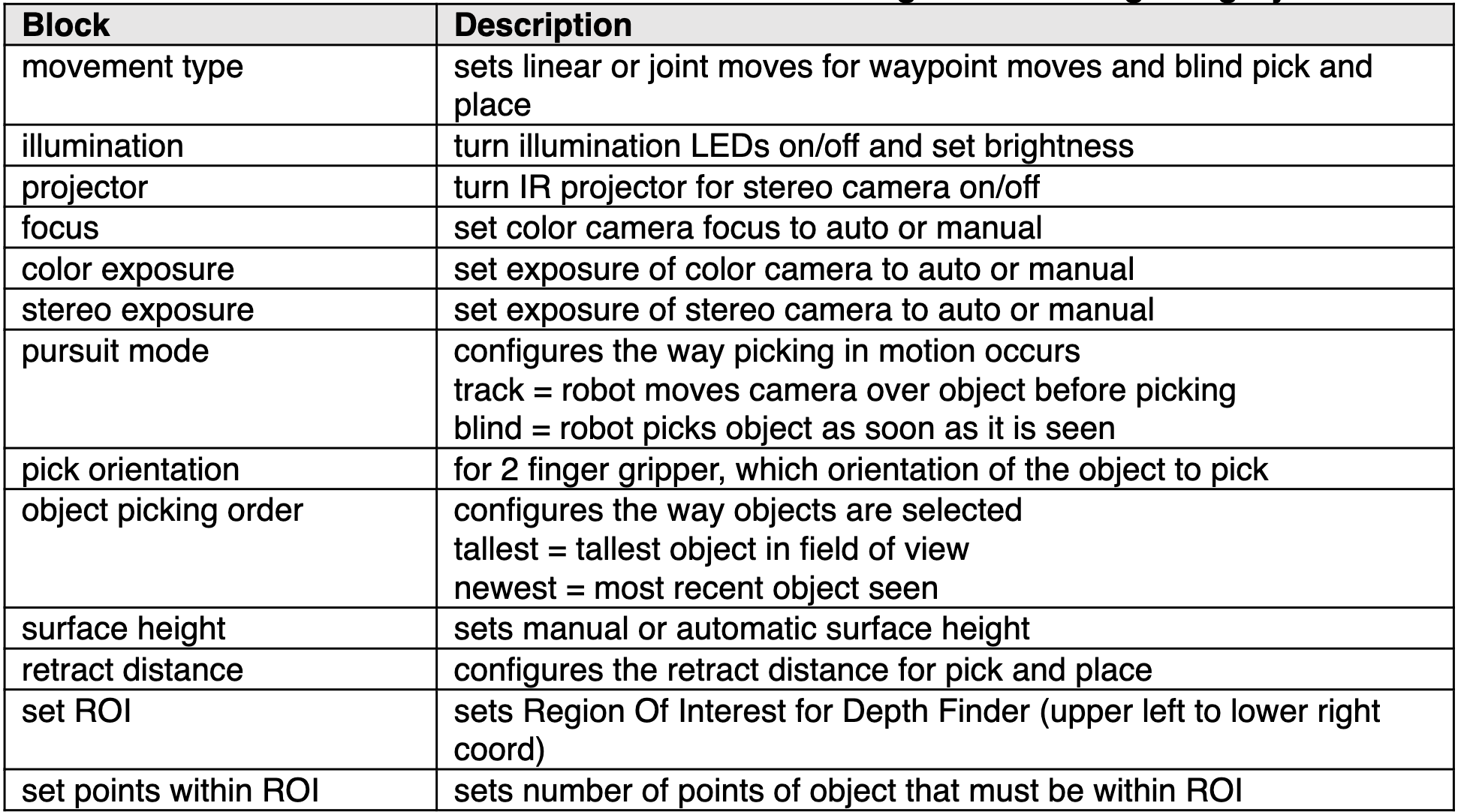
Figure 40: Config blocks
Sample Programs
The next few pages illustrate some sample programs that demonstrate the simplicity of creating powerful robotic tasks.
Visual Pick and Blind Place
The simplest example of a visual pick and blind place is shown in Figure 41. When the Start button is pressed, the robot moves to the waypoint PickZone. It visually picks the object Box, whether it is statically within the field of view or if it is moving, such as on a conveyor. Once the object has been picked, the robot moves to the waypoint PlaceZone and sets the object down.
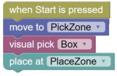
Figure 41: Simple visual pick and blind place
Visual Placement of an Object on another Object
Figure 42 shows a simple example of visual placement of a deck of cards onto a box. Because an object may obscure the camera once it’s picked, the robot moves to the place zone, and the camera records the location of the box in the variable TopOfStack. Then the cards are picked from the PickZone. Using the “place on” block, the cards are placed on top of the previously recorded visual location of the top of the box, automatically offset by the height of the object that was picked (the cards).
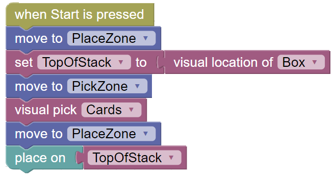
Figure 42: Visual placement
Visual Pick from Conveyor and Palletize
Figure 43 shows a palletizing example. Six cards are picked from a conveyor and palletized on a grid of 3x2. Pursuit mode is set to track to optimize the performance of picking in motion. The retract distance is customized to ensure that the cards are lifted off the conveyor high enough to let other objects move beneath. After picking the cards, the robot is moved to the PlaceZone, above the pallet. The four corners of the pallet are defined by waypoints BL, BR, TL, and TR. The grid pattern is specified 3x2 with L-R positions and T-B positions. A multi-layer palletization can occur because the height is specified as the height of the cards object. The ApproachXY and ApproachZ are specified to ensure a tight packing of the cards. The variable cards is used to index through the pallet.
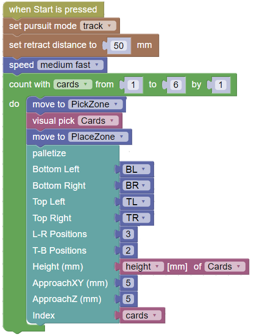
Figure 43: Visual Pick from Conveyor and Palletize
Visual Stacking
The concepts involved in visual placement can be expanded to implement visual stacking (Figure 44). The program starts exactly the same way as the visual placement example from Figure 43. The top of the box is visually located and saved in the variable TopOfStack. Four cards are sequentially picked using the repeat loop and the move to PickZone and visual pick of Cards. Each card is visually placed on the top of the stack using the “place on” block. After a deck of cards has been placed, the robot moves to the PlaceZone and locates the new top of the stack using the “visual location of Cards” block to update the TopOfStack variable. Powerful visual placement programs can be developed using these concepts.
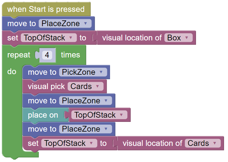
Figure 44: Visual Stacking
Visual Sorting
Figure 45 shows an example of visual sorting of Boxes and Cards from a conveyor. This program assumes that Box and Cards are the only objects that have been learned (in the workspace where the program resides). This allows a very simple visual picking block of “visual pick Known Object”. The robot is at the PickZone and waits for either a Box or Cards to be seen coming down the conveyor. It picks the object, whatever it is, and the identity (name) of the object is available in the “current picked object” block which is used with an “if” statement to check if the picked object matches either the Box or the Cards. Different actions (such as placing on a particular conveyor) can be performed based on whatever object was picked. Complex visual sorting tasks can be accomplished using these methods.
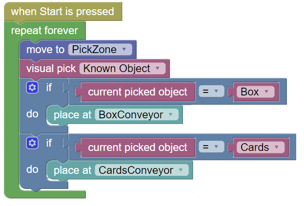
Figure 45: Visual Sorting